Retrohacking the ATL Access 3 probe
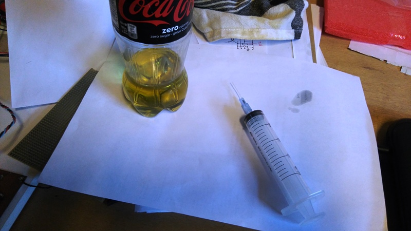
What does it look like?
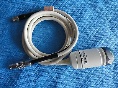
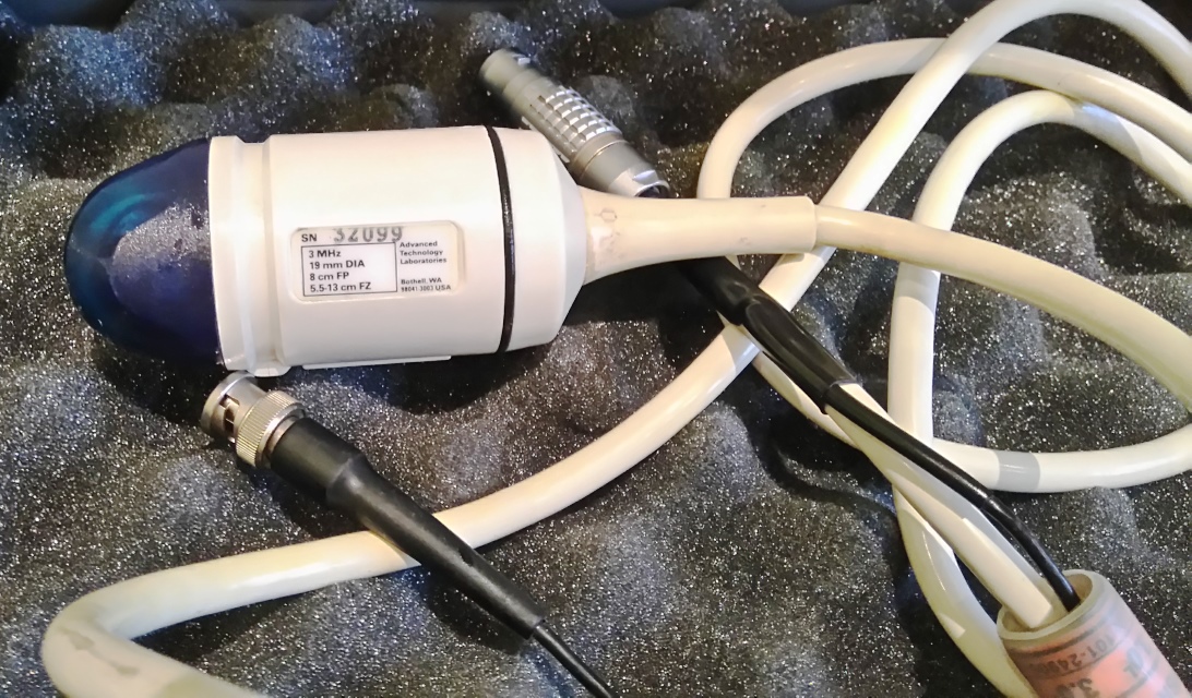
Information
What is it supposed to do?
The aim of this echOmod is to get the mechanical movement of the piezos. Salvaged from a former ATL3.
How does it work: block diagram
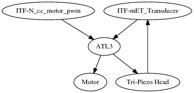
ITF-mET_Transducer->ATL3->Tri-Piezo Head->ITF-mET_TransducerITF-N_cc_motor_pwm->ATL3->Motor
About the module
Pros
- Simple to use
- 3 piezos, can be of different frequencies as for the ATL10PV
Cons
- We have removed the position system : we don't have the encoding system
- Tough to find a old ATL Access 3 probe
Constraint and limits
- For using the ATL Access 3, the 3.3V can be used directly from the power supply -- see this page.
Discussions
Existing documentation
- We have found an interesting doc: the ATL manual for the ultrasound machine - and specs for the whole set of transducers -- found here
Details of the probe
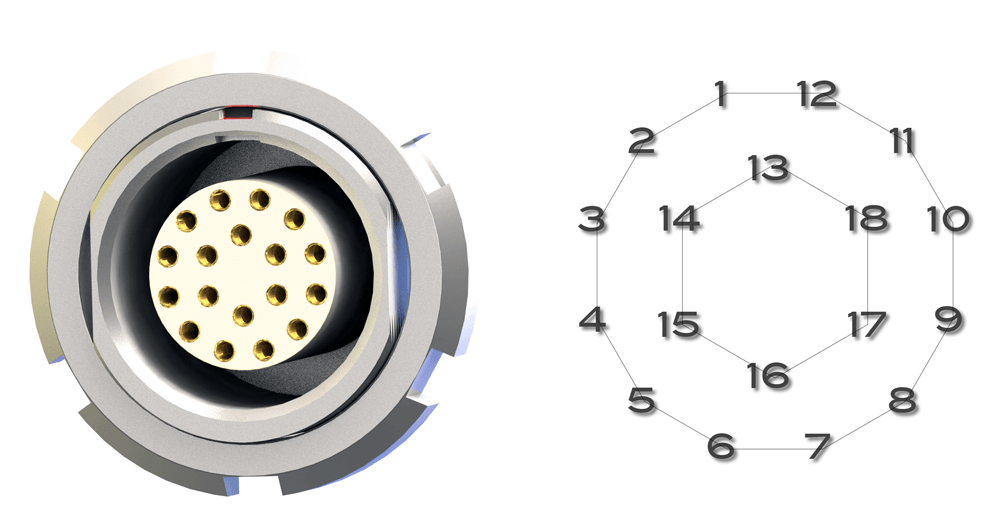
What are the pins ?
The pins layout is numbered below. The following pins have been identified:
- Pins 9 and 10 are for motor control
- GND are pins 2, 4 and 14
- VCC for counter is on pin 17
- CounterSignal is on pin 18
Using numbering as on breakout pins:
- Pack of signals together on 7/8/9/10/11 (which are the 5+1 on the 3x2 header in the head: counter ?)
- impedance is 2.56, 9.5, 8.4, 2.57, 1.279, 9.61 Ohm. 4 sets of impedance: R, 2R, 8.4, 8.4+R
- 4x1 header is connect to 4,3, 7 and (?? missing GND ?) which seems to be an eeprom. worth checking Vss and Vdd for these).
- 6.5 Ohm between 7 and 12. What can it be?
- Motor seem to be on 16-17
- Pin 4 is shared, in front of pin 7. (pin 7 alim, 4 is GND ?)
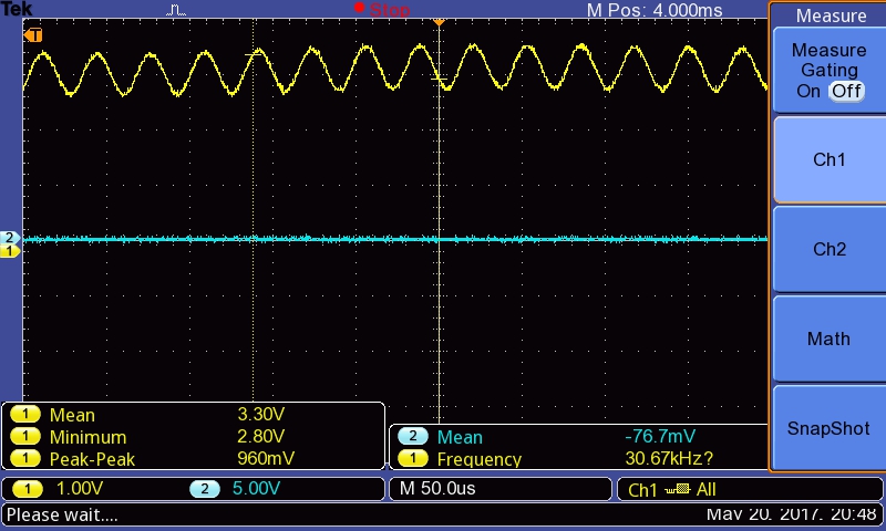
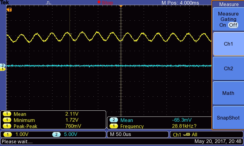
Testing the counter for probe turns
Using this arduino code. Some stuff still to do:
- In the code, adding a marker for the beginning of a number
- Are 6 bit sufficient?
- Better control of the pulse counter.
Replacing the oil
Oil to be found to replace lost one =) Feeback: linseed oil seems good !
Refilling? see below:
Where to source?
Mostly ebay:
- 60$ for 1 probe - - http://www.ebay.com/itm/ATL-Access-C-3-0-MHZ-12-7mm-dia-Ultrasound-Transducer-P-N-101-25909-72-3862-/111898969844?hash=item1a0db2c6f4:m:mY5GvKHR7qPhPuufxAHnjyA
- 290$ for 2 probes - 2x ATL Access A (3MHz) - http://www.ebay.com/itm/ATL-Access-A-Ultrasound-Probe-LOT-2-/131588905820?hash=item1ea34f5b5c:g:COUAAOSwyQtV3Xkg
- 5MHz @ http://www.ebay.com/itm/ATL-Access-A-5-0MHz-12-7mm-Dia-6cm-FP-Ultrasound-Probe-3359-/111904941527?hash=item1a0e0de5d7:m:m35HcHQafc7p8BdFvI01GZg (104$)
How to connect the motor?
I have not used any feedback action, just tried to provide a constant voltage.
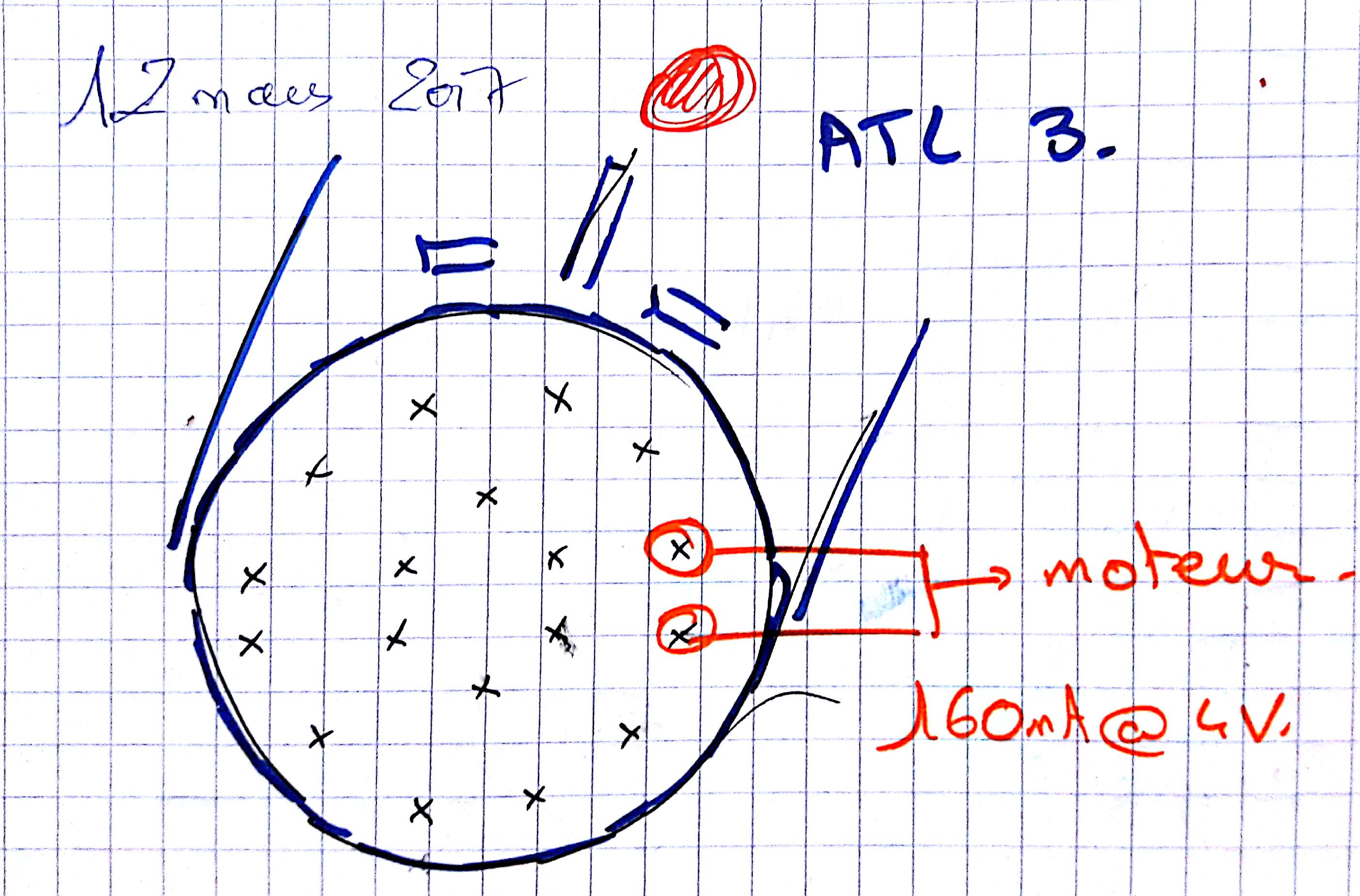
Using 160mA@4V
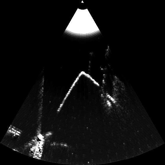
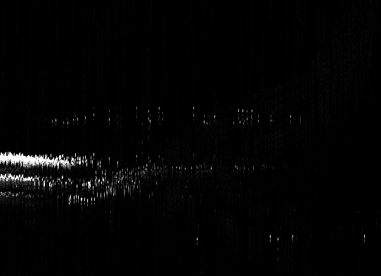
Good images achieved! [RESOLVED]
Please refer to this log to read more about how we got this image. Here's an example of the image we got:
RealTime issues [RESOLVED]
The motor spins too fast... damned. As seen in "rotating probe image", we can't really say when the probe is rotating or not. So we'll need a way to check the speed of the motor.
Having timestamped the bitscope acquisitions, there is a 20 +- 0.74 ms between each line.. a tad slow.
Real time achieved
Getting realtime information (with no stupid data transfer delays) gives continuous images, using a Beaglebone PRUDAQ.
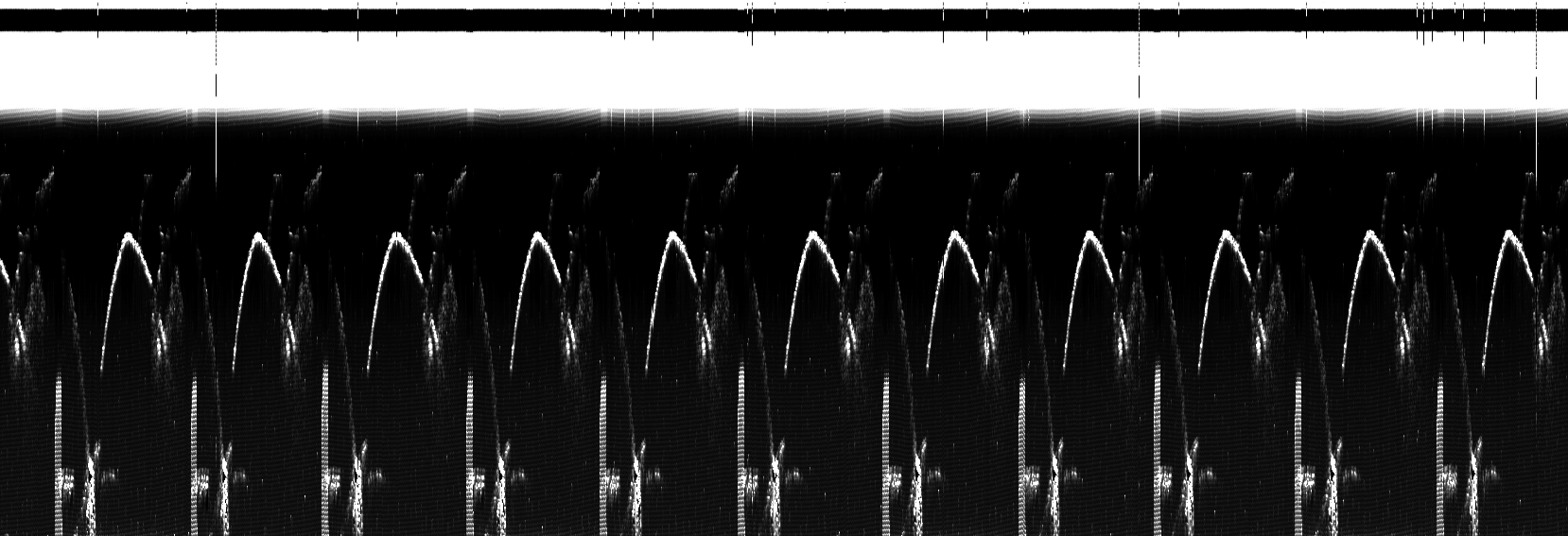
Reconstructing one loop
With which one can reconstruct a movie:
Trying to sort out the details
We see that the image is there, but we don't know when/where the image was taken. See the reference page for this old probe.
This data comes from the Murgen project, Worklog 10
Tests [RESOLVED]
Those were done with a bitscope at 5Msps.. with 'non-null' delays between each line.
Find a connector
BNC female to SMA male
What ICs are inside the head?
And how are the signals prepared? See this work for pictures of the ICs inside, and for the type of signals inside the head of the probe.
Signals ?
There's going to need to signal hacks to remove constant components from the signals

4x1 header : EEPROM ?
[dm74s287](http://www.yd-tech.com.tw/pdf/74S/74S287.pdf
HEF4040BT : 12-Stage Binary Ripple Counter
Want to know more about electrical impedance?
Some resources:
- http://www.biosono.com/PrmtLgd/PrmtLgd.php?id=TrnsRlc
http://alejandria.ccm.itesm.mx/biblioteca/digital/liele/pcmc.pdf
Impedance matching? See https://www.ncbi.nlm.nih.gov/pubmed/23443705
TODO
- Determine the impedance of the transducer seen by tobo (@ulb ?)
- Do a logic control of the probe
- Do some impedance matching (@ulb ? @will ?)
- Finding more precise pins mapping
DONE
- BONUS! Get RealTime acquisition
- Finding the pins mapping
- Acquire and build ultrasound pictures =)
- Motor in action
- Refill Oil
- Test echoes
- Make and insert a video: there
People
- @eiffel for playing with hardware together