2017-05-20
Content
Counter going in:
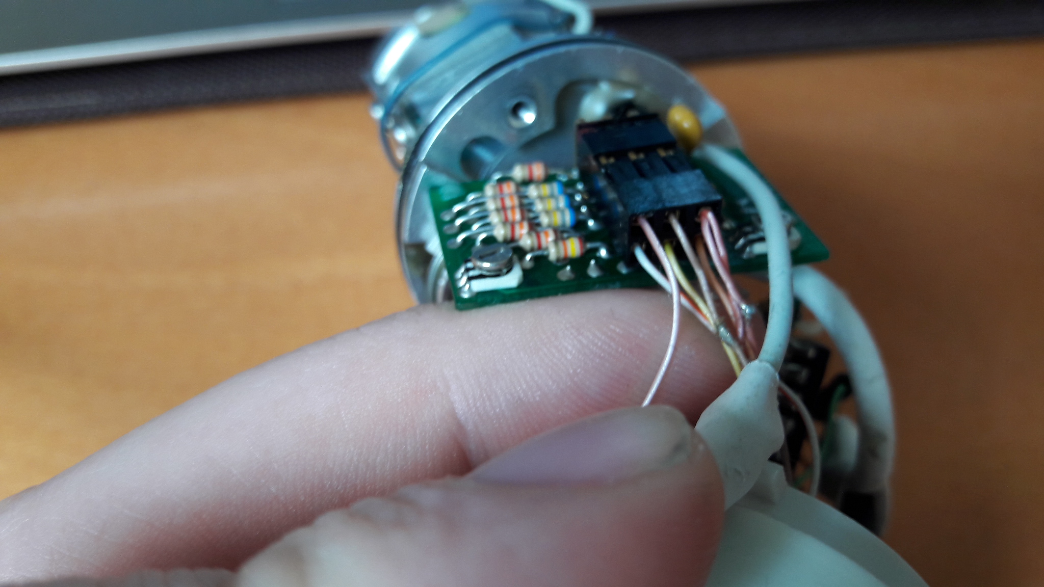
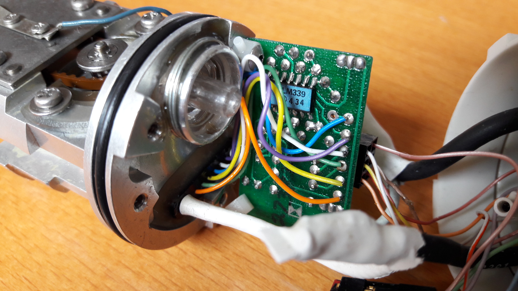
1st board: counter: 6 wires going out of counter, 6 feeding in LM339, 6 wires going out. LM339 is Quad Differential Comparators
2nd board:
- DM74S287AN: 1 green wire coming from ultrasound machine, 1 connected to LM339, 3 others from machine. Seems a schottky memory 256x4 1024-bit TTL PROM. The 4 pins on this side seem to go to Q0 to D3. Only Q3 is connected to green wire.
- HEF4040BT: a 12-stage binary ripple counter. VDD from 3V to 5V. VDD is fed through the "salmon" wire. CP (Clock) is Wire4 (blue)
Guesses
- DM74S287AN stores the probe number / serial / ...
- The LM339 plays with the sensor.
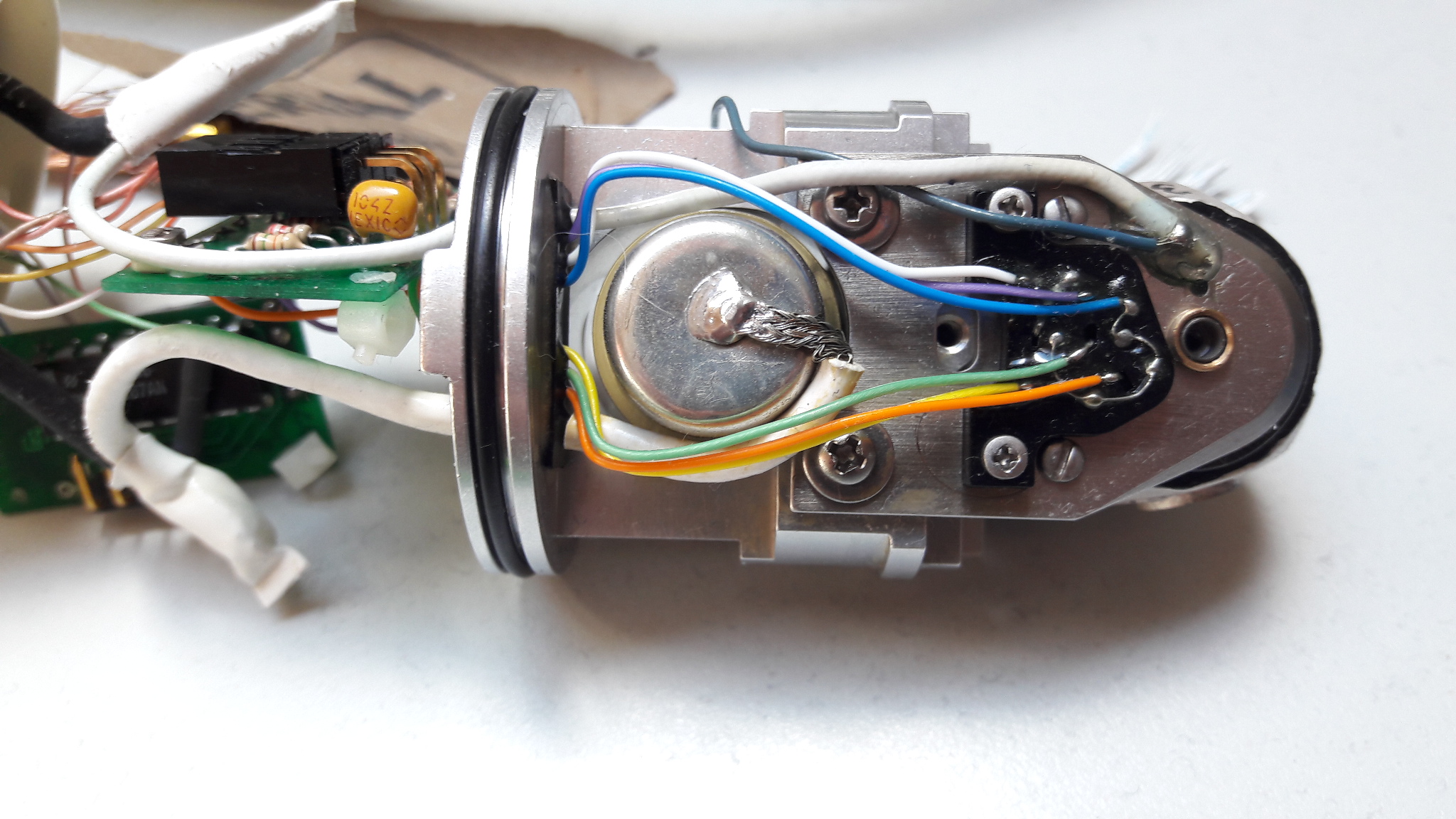
Images
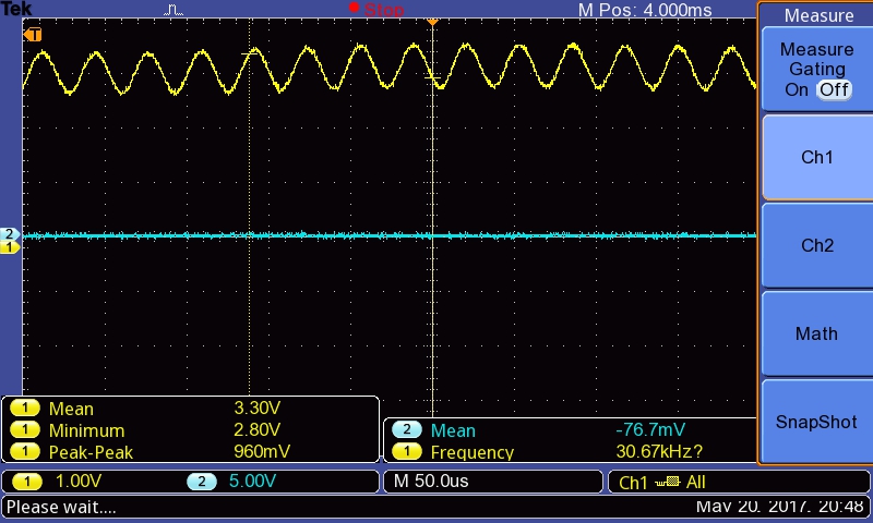
From the last image, data from the wires from the sensors
- Blue -> 5V
- White -> 2.2V
- Yellow -> 3.6V
Orange
20ms of period, that's 50Hz, that could be 50 imgs per sec, or since the periods seem divided in three, maybe that's a full turn of the head, so 3 images.

Green
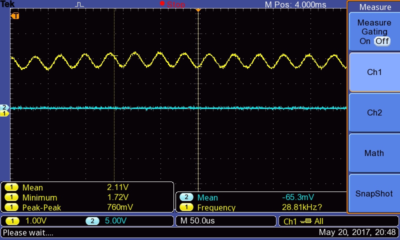
The others are 28 to 30kHz, 30us/period. That's a period 1/600 of the period above. That can therefore be 600 lines / image, or rather
Violet
Sensors
Pins
9 et 10: motor (which one is the GND?)
16 and 2: what are those?
- 18 + 18
- 17 GND
Next steps
- Power the motor
- Connect intelligence on 16 and 18
- Try powers around 17 and around
Possible encoders
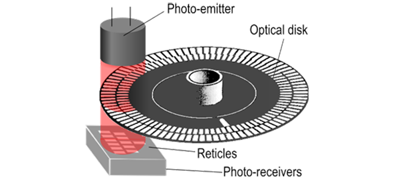
PINS