This is the module which emulates the signal coming from the analog processing chain.
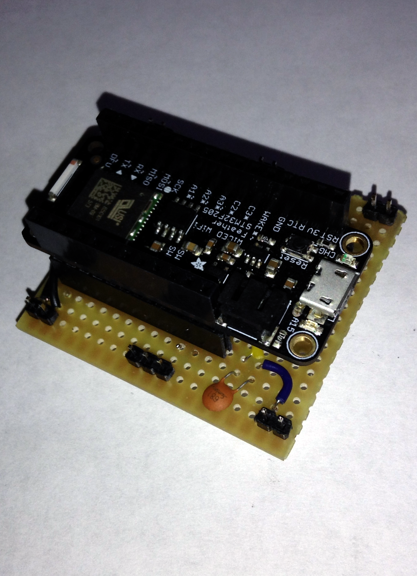
What does it look like?
Information
What is it supposed to do?
The aim of this echOmod is to simulate a raw signal that would come from the piezo and analog chain.
How does it work: block diagram
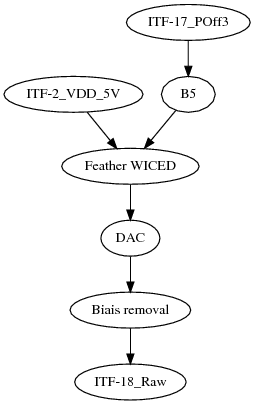
ITF-2_VDD_5V->Feather WICED->DAC->Biais removal->ITF-18_RawITF-17_POff3->B5->Feather WICED
About the module
Pros
- TBD
Cons
- TBD
Constraint and limits
Setup the module
- Install Arduino-IDE according to the adafruit page on the Feather WICED starting here.
- Flash the WICED libs
- Install the Generator arduino code
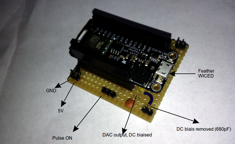
- Connect the trigger on B5 --
TRIG_PIN = PB5; - Biaised output will be on A4 (
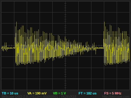
DAC_CH1), you can remove the biais with a capa in series (681 / 680pf works) - Output will be a small (+-50mV) output mimicking an 2MHz decreasing signal, along with 3 peaks of 1 period, 2 periods and 4 periods, of decreasing intensity.
Getting a signal
With a simple code on feather WICED, managed to get a 1.8 - 2Mhz signal ( code is here ) - and worklog is here.
Look of the module
The pins needed to be rerouted, so an intermediary board was made ouf of stripboard
The interrupt was brought done to 3.3V instead of the 5V coming from the trinket pro, routed to pin B5.
Result with Goblin, the analog processing
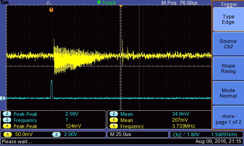
Signal out of DAC
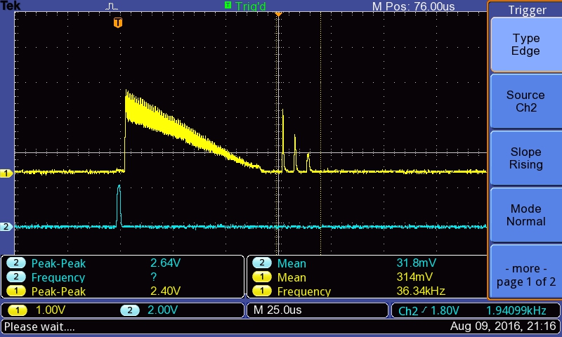
Signal out of Goblin
Why not a Feather WICED ?
Interrupts:
If similar to the Feather M0Proto
#0 / RX - GPIO #0, also receive (input) pin for Serial1 and Interrupt 2#1 / TX - GPIO #1, also transmit (output) pin for Serial1 and Interrupt 3#2 / SDA - GPIO #2, also the I2C (Wire) data pin. There's no pull up on this pin by default so when using with I2C, you may need a 2.2K-10K pullup. Also Interrupt #1#3 / SCL - GPIO #3, also the I2C (Wire) clock pin. There's no pull up on this pin by default so when using with I2C, you may need a 2.2K-10K pullup. Can also do PWM output and act as Interrupt 0.
Why not a Teensy ?
Simplement (TEENSY) pour émuler un signal. A "high" speed DAC is required. Since the acquisition period is 200us, we should have say 2 periods over this, hence a period of 100us, that's a 10kHz signal we should see. At 20 pts per period, we should have roughly a 200kHz DAC.
- https://www.pjrc.com/teensy/td_timing_elaspedMillis.html
- https://forum.pjrc.com/attachment.php?attachmentid=2790&d=1413271011
- Pin Change teensy: https://www.pjrc.com/teensy/interrupts.html
Discussions
TODO
DONE
- Feather: work with an interrupt
- Write code for feather WICED
- Publish this code
- Remove Signal Bias
- Validated with a Feather WICED (code).
- Feather: remove the average value before inputing in Goblin
- Check output with Goblin
People
- Kelu