General principles of ultrasound imaging
Using echoes to map interfaces
Medical ultrasound is based on the use of high frequency sound to aid in the diagnosis and treatment of patients. Ultrasound frequencies range from 2 MHz to approximately 15 MHz, although even higher frequencies may be used in some situations.
The ultrasound beam originates from mechanical oscillations of numerous crystals in a transducer, which are excited by electrical pulses (piezoelectric effect). The transducer converts one type of energy into another (electrical <--> mechanical/sound).
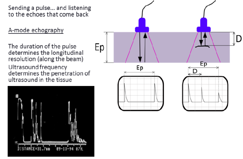
The ultrasound waves (pulses of sound) are sent from the transducer, propagate through different tissues, and then return to the transducer as reflected echoes when crossing an interface. The returned echoes are converted back into electrical impulses by the transducer crystals and are further processed - mostly to extract the enveloppe of the signal, a process that transforms the electrical signal in an image - in order to form the ultrasound image presented on the screen.
Ultrasound waves are reflected at the surfaces between the tissues of different density, the reflection being proportional to the difference in impedance. If the difference in density is increased, the proportion of reflected sound is increased and the proportion of transmitted sound is proportionately decreased.
If the difference in tissue density is very different, then sound is completely reflected, resulting in total acoustic shadowing. Acoustic shadowing is present behind bones, calculi (stones in kidneys, gallbladder, etc.) and air (intestinal gas). Echoes are not produced on the other hand if there is no difference in a tissue or between tissues. Homogenous fluids like blood, bile, urine, contents of simple cysts, ascites and pleural effusion are seen as echo-free structures.
Creating a 2D image
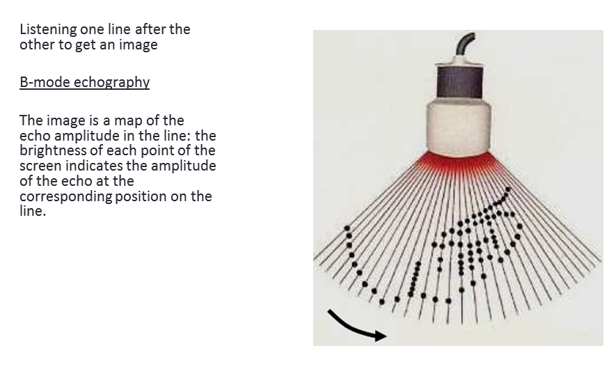
If the process is repeated with the probe sweeping the area to image, one can build a 2D image. In practice, in the setups we'll be discussing, this sweep is done with a transducer coupled to a servo, or using a probe that has an built-in motor to create the sweep.
Ultrasound hardware structure
To produce an image, the modules have to create a high voltage pulse, which excites a transducer. Echoes coming from the body are amplified using a TGC + LNA, which cleans the analog signal, which itself gets digitalized.
The diagram is represented below:
Transducer
A critical component of this system is the ultrasound transducer. A typical ultrasound imaging system uses a wide variety of transducers optimized for specific diagnostic applications, but in our case, we'll limit the costs.
High-Voltage Transmitters (see the module)
A digital transmit beamformer typically generates the necessary digital transmit signals with the proper timing and phase to produce a focused transmit signal. High-voltage pulsers quickly switch the transducer element to the appropriate programmable high-voltage supplies to generate the transmit waveform. To generate a simple bipolar transmit waveform, a transmit pulser alternately connects the element to a positive and negative transmit supply voltage controlled by the digital beamformer. More complex realizations allow connections to multiple supplies and ground in order to generate more complex multilevel waveforms with better characteristics.
TGC + LNA = Variable-Gain Amplifier (VGA) (see the module)
The LNA in the receiver must have excellent noise performance and sufficient gain. In a properly designed receiver the LNA will generally determine the noise performance of the full receiver.
The VGA, sometimes called a time gain control (TGC) amplifier, provides the receiver with sufficient dynamic range over the full receive cycle. Ultrasound signals propagate in the body at approximately 1540 meters per second and attenuate at a rate of about 1.4dB/cm-MHz roundtrip. Immediately after an acoustic transmit pulse, the received "echo" signal at the LNA's input can be as large as 0.5VP-P. This signal quickly decays to the thermal noise floor of the transducer element. The dynamic range required to receive this signal is approximately 100dB to 110dB, and is well beyond the range of a realistic ADC. As a result, a VGA is used to map this signal into the ADC. A VGA with approximately 30dB to 40dB of gain is necessary to map the received signal into a typical 12-bit ADC used in this application. The gain is ramped as a function of time (i.e., "time gain control") to accomplish this dynamic range mapping.
Anti-Alias Filter (AAF) and ADC (see the module)
The AAF in the receive chain keeps high-frequency noise and extraneous signals that are beyond the normal maximum imaging frequencies from being aliased back to baseband by the ADC. Many times an adjustable AAF is provided in the design. To avoid aliasing and to preserve the time-domain response of the signal, the filter itself needs to attenuate signals beyond the first Nyquist zone. For this reason Butterworth or higher-order Bessel filters are used.
The ADC used in this application is typically a 12-bit device running from 40Msps to 60Msps. This converter provides the necessary instantaneous dynamic range at acceptable cost and power levels. In a properly designed receiver, this ADC should limit the instantaneous SNR of the receiver. As previously mentioned, however, limitations in the poor-performing VGAs many times limit receiver SNR performance