lite.tbo: the bipolar HV-pulser
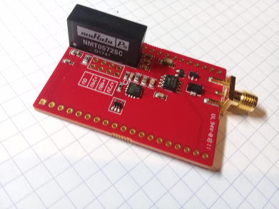
What does it look like?

Information
What is it supposed to do?
The aim of this echOmod is to get the HV Pulse done.
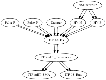
How does it work: block diagram

Pulse-P->TC6320TGPulse-N->TC6320TGDamper->TC6320TGNMT0572SC->HV-N->TC6320TGNMT0572SC->HV-P->TC6320TG->ITF-mET_TransducerITF-mET_Transducer->ITF-mET_SMAITF-mET_Transducer->ITF-18_Raw
About the module
Pros
- Cheaper, more robust than tobo
- Less issues with the MD0100
Cons
- As of today (20180305), the damper still lacks
Constraint and limits
Testing
Brief
Specs
- Needed to get a couple of 10's of ns wide square pulses, both in the positive and negative.
- Control of pulses must be through 3.3 or 5V tolerant logic
- Pulses height must be selectable (say with a jumper?) for ~20V, 40V, 80V (for positive pulses).
- Only power supply available is 5V
Components
- See this application note - recommend MD1213 and TC6320
- Possible (but not used in the end) high voltage source: https://datasheets.maximintegrated.com/en/ds/MAX5025-MAX5028.pdf (3 -> 30V) to be used with a 555 DC-DC convertor
- Signal back from the diod is clipped by MD0100 + back to back diods.
Build docs
Power use
- Needs only 5V
Components
- HV: NMT0572SC
- Pulser : MD1213 and TC6320 -> see Fig.6 here, bipolar 3 level pulser.
- TC6320, undamped, detailed here.
- TC6320 http://ww1.microchip.com/downloads/en/DeviceDoc/20005697A.pdf for the datasheet
- Protection: MD0100+diods -- should be enough, see bottom of page 1, or Fig 9
Discussions
TODO
- Review a bipolar design (originally alt.tbo -- but double the components and hence the price)
DONE
- Preliminary testing
People
- Ivan for the TC6320TG