Session 6 - 28 March 2016 - Imaging the fantoms, BitScope version
Previous sessions
- Session 1 : Powering the board, power use, first (bad) trigging and echoes (06 March 2016)
- Session 2 : Non-controlled pulsing, inverters, better echoes (11 March 2016)
- Session 3 : Getting controlled pulsing, but width not controlled (15 March 2016)
- Session 4 : Width of the pulses is getting controlled =) (19 March 2016)
- Session 4b : Simple data visualisation with BitScope (19 March 2016)
- Session 5 : moving the transducer to get the first image (20 March 2016)
- Session 6 : Getting a clinically usable image (28 March 2016)
- Session 7 : Getting cleaner images - code improvements (3 April 2016)
- Session 8 : Comparing acquisition speeds (3 May 2016)
Today
Goal
- Getting an actual image of a phantom through the BitScope tool.
- Using the TGC
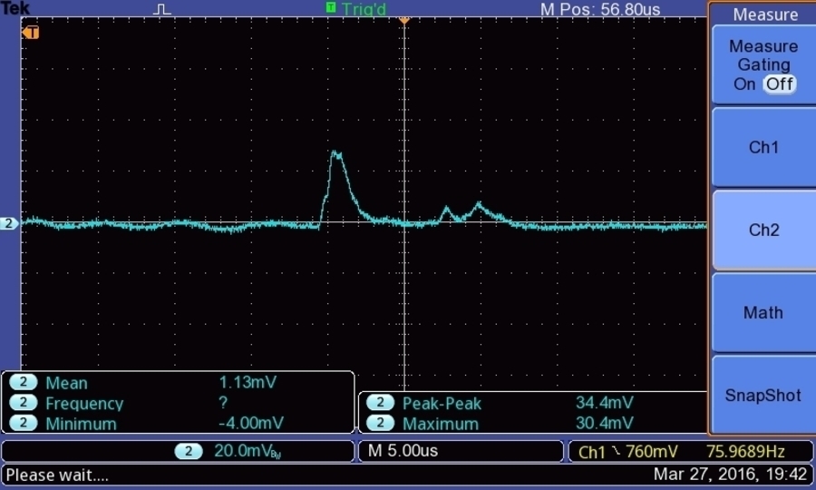
- Using the enveloppe detector (around 3.5MHz, but we used a 4MHz transducer.. still..)
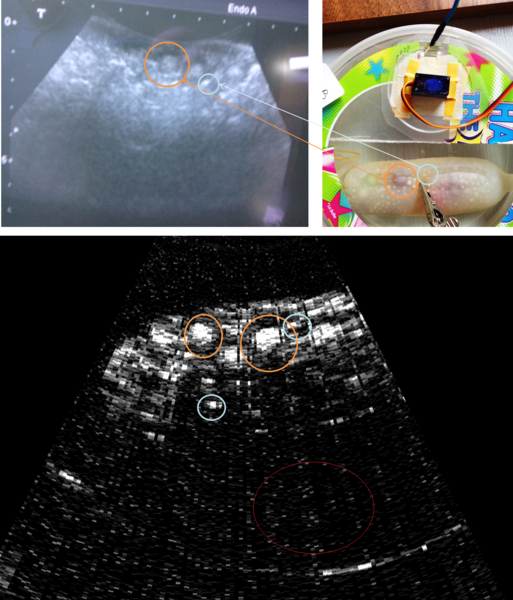
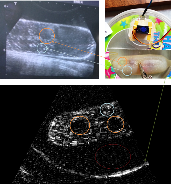
TL;DR: Comparing Images
Not too bad =)
Fantom 1
Fantom 2
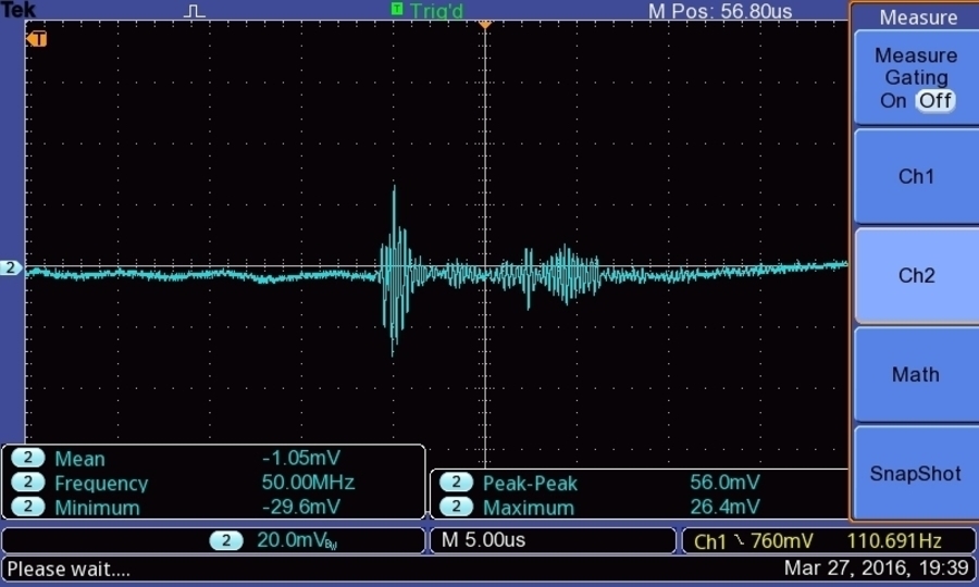
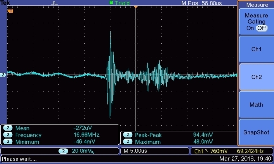
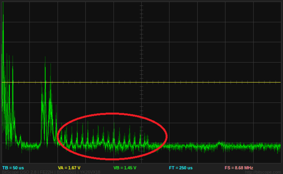
Bitscope signal
In red is the noise that the BitScope "randomly" adds to the signal (the same as the noise pattern seen in the comparison above)
Setup
Organization
- Same as previously... Session 5
- Just adding the alim to feed TP4 (Analog gain of the TGC) -> around to 900mV and 40mA)
- Had to unplug TP4/5 and plug it into the transfo
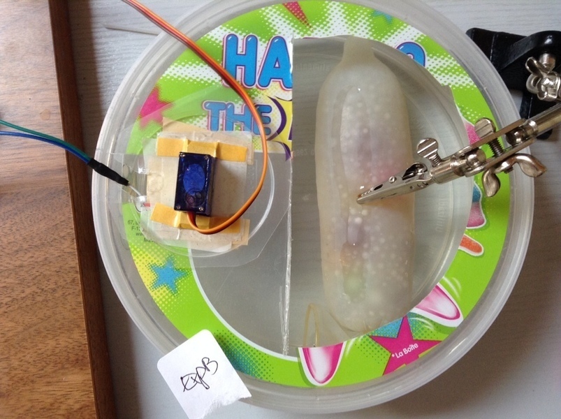
- Layout out the fantoms:
Remarks
- Same setup as Session 4, and same remarks apply.
- Not using the SPI, only Analog Gain, which we max. We can reduce the gain artificially in the software.
Give me files
- The code lies at
bitscope/full_image/Session_6a/acquire_image.pyto acquire a full image - The data for images is in the
bitscope/full_image/Session_6a/ExpX/raw_data/*.log - Creating data files (.data) from the logs is at
bitscope/full_image/Session_6a/CreateImage.py - Creating Nearest neighbours Scan Conversion is
`bitscope/full_image/Session_6a/CreateNN.py - Creating 4Tap is
`bitscope/full_image/Session_6a/CreateSC.py - Bulking image creations is at
bitscope/full_image/Session_6a/BatchImage
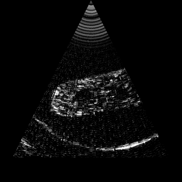
Give me an image
Discussion and issues
Discussion
- Had to unplug TP4/5 and plug it into the transfo
- Had to feed in max V to the TP4 (Analog gain of the TGC) -> around to 900mV and 40mA)
- Gain formula: Gain(depth)= (1.9*(depth)^(0.6)/(Depth^(0.6))) -> it quite lowers the signal close to the transducer, and raises the end of the signal.
Issues
- Had to change the back and forth sweeping of the servo.. else the two sets of lines are intertwinned as you'll see with Session-6 data instead of Session-6a(
bitscope/full_image/Session_6/BatchImage) - Bad noise was coming from the computer
- Some residual noise coming from the bitscope (the small signal between 100us and 250us):

Next steps
- Plugging into the BBB
Images
Getting an image from TP1
Getting an image from TP2
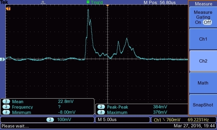
Getting an image from TP8 - enveloppe (20mV/div). TP4: 80mV / 22mA
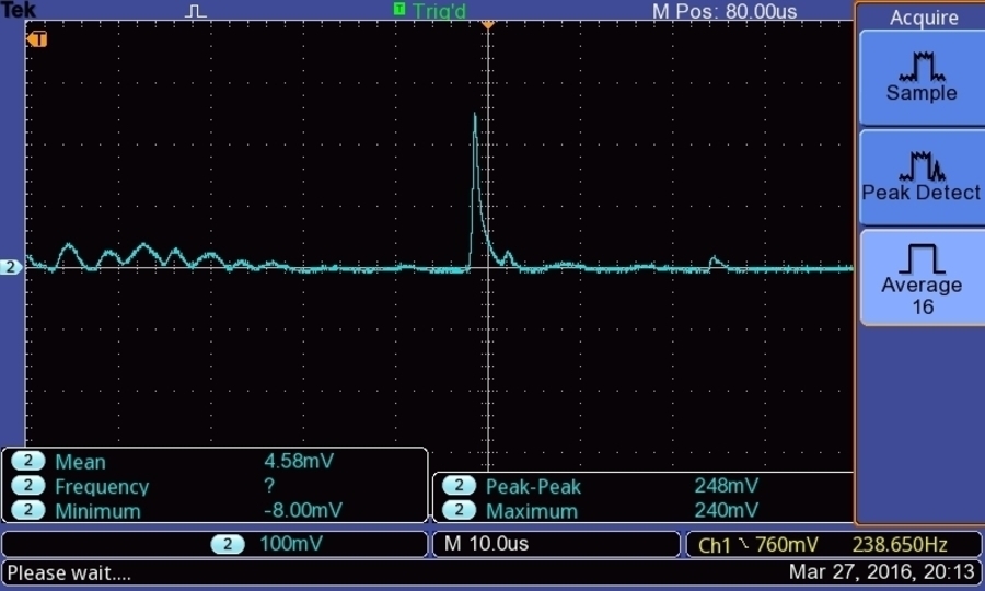
Getting an image from TP8 - enveloppe (100mV/div). TP4: 480mV / 41mA
Getting an image from TP8 - Front and back of the fantom (100mV/div). TP4: Off
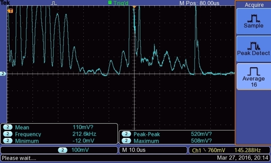
Getting an image from TP8 - Front and back of the fantom (100mV/div). TP4: 480mV / 41mA
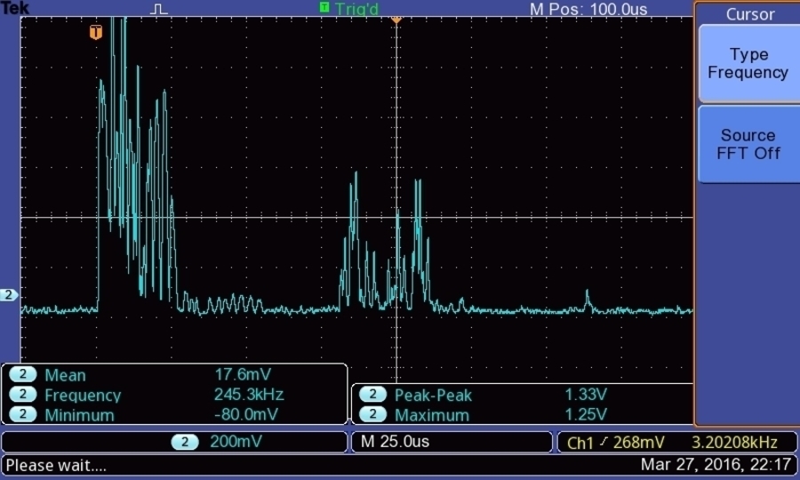
Getting an image from TP8 - A-Scan of the fantom, plus wall of the basin (200mV/div). TP4: 480mV / 41mA
TrinketPro code
Code is at bitscope/TrinketProCode
/*
  SimplePulse (simple way)
  Using the Hackaday Trinket Pro.
  Creates two contiguous pulses one after the other, then sleeps till the next time.
  This example code is in the public domain. Inspired from Blink.
 */

#include <Servo.h>

Servo myservo;  // create servo object to control a servo
                // a maximum of eight servo objects can be created

int pos = 60;    // variable to store the servo position

void setup()
{
  myservo.attach(5);  // attaches the servo on pin 5 to the servo object
  DDRB = B11111111; // set PORTB (digital 13~8) to outputs
}


void loop()
{
  for(pos = 60; pos < 120; pos += 1) // goes from 60 degrees to 120 degrees
  {                                  // in steps of 1 degree
    myservo.write(pos);              // tell servo to go to position in variable 'pos'
    delay(40);                       // waits 12ms for the servo to reach the position
    PORTB = B00001000;               // Pin 11
    delayMicroseconds(pos);          // microsecondes
    PORTB = B00010000;               // Pin 12 = pulse positif
    __asm__("nop\n\t");
    PORTB = B00100000;               // Pin 13  = pulse negatif
    delayMicroseconds(1);
    //__asm__("nop\n\t""nop\n\t");
    PORTB = B00000000;
    delayMicroseconds(1000);          // microsecondes
        PORTB = B00001000;               // Pin 11
    delayMicroseconds(pos);          // microsecondes
    PORTB = B00010000;               // Pin 12 = pulse positif
    __asm__("nop\n\t");
    PORTB = B00100000;               // Pin 13  = pulse negatif
    delayMicroseconds(1);
    //__asm__("nop\n\t""nop\n\t");
    PORTB = B00000000;
    delay(10);
  }

    myservo.write(60);              // tell servo to go to position in variable 'pos'
    delay(1000);                       // waits 1000ms for the servo to reach the position


}
