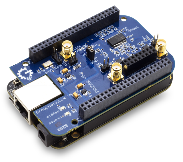
This is the module to get high-speed (40Msps) signal acquisition.
What does it look like?

Information
What is it supposed to do?
The aim of this echOmod is to simulate the enveloppe (or maybe soon the raw signal) that would come from the piezo and analog chain.
How does it work: block diagram

ITF-B_5v->BBB->PRUDAQ->BBB->FileITF-E_signal_envelope->PRUDAQBBB->SPI->TFT Screen
About the module
Pros
- Dual-channel simultaneously-sampled 10-bit ADC
- Up to 20MSPS per channel (40MSPS total) (but see below)
- 0-2V input voltage range (DC coupled)
- 4:1 analog switches in front of each channel provide a total of 8 single-ended analog inputs. (See here for differential input)
- SMA jacks for direct access to the 2 ADC channels
- Flexible clock options:
- External input via SMA jack
- Internal onboard 10MHz oscillator
- Programmable clock from BeagleBone GPIO pins
Cons
- Input signals outside the 0-2V range may damage the ADC
- Inputs are DC-coupled
- We provide a 1V reference for mid-scale, but it's unbuffered
- At 40MSPS the 1GHz ARMv7 only has 25 cycles per sample (and at least 25% of that is eaten by DMA overhead)
- Round-robin sampling across the 8 analog inputs is tricky
- As the previous section points out, you can buffer samples into the 512MB of main memory, but there's no way to get the samples into storage or off the board at the full 40MSPS data rate
Constraint and limits
The 0-2V limit
The enveloppe signal (0-3.3V) coming from Goblin is clipped beforehands with 2 diodes, giving a 0-1.5V range with easy components.
Testing the analog processing board with the PRUDAQ
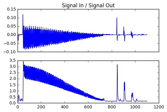
Data sampled at 10Msps on the PRUDAQ on both channels.
See the Jupyter notebook In-Out.ipynb
Data is saved here. It's 32Mb of sampling at 10 Msps.
Signal in / signal out
The signal sent in is 50mVpp, the carier is at 2MHz. Linear decrease from t0 to the end.

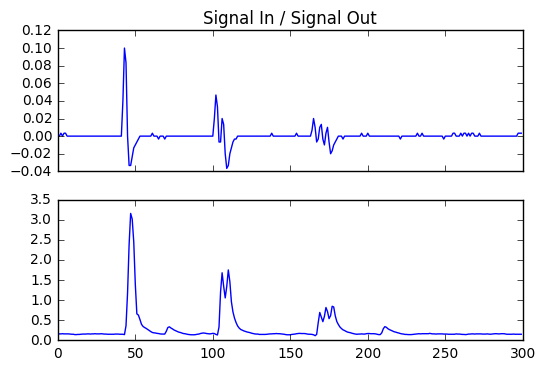
Details at the enveloppe level
The period of the signal is 2 MHz. The first peak has 1 period, the second 2, height is half of the first peak, and the 3rd has 3 periods, height 1/4th of the first peak.

Learn more
From BeagleLogic:
Learning more about BeagleLogic:
- https://github.com/abhishek-kakkar/BeagleLogic/wiki
- https://github.com/abhishek-kakkar/BeagleLogic/wiki/sysfs-attributes-Reference
BeagleLogic can be used stand-alone for doing binary captures without any special client software.
dd if=/dev/beaglelogic of=mydump bs=1M count=1
is sufficient to grab a binary dump, once sample rate has been configured. This can be done via sysfs, but in our case, I just used the onboard 10MHz clock, and selected it with the on-board clock-selection jumper.
Install
- The image that I used for this PRUDAQ module was available via Abhishek on google docs
- One can also use a eMMC flashed
and read the quickstart,
dd if=./beaglelogic-prudaq-system.img of=/dev/mmcblk0 bs=1M count=1
An interesting read to expend the file system : Read more.
Vitesse d'acquisition
sudo dd if=/dev/beaglelogic of=dual_entry.bin bs=1M
debian@beaglebone:~$ sudo dd if=/dev/beaglelogic of=sonde3V_1.bin bs=1M count=3232+0 records in
32+0 records out
33554432 bytes (34 MB) copied, 0.939505 s, 35.7 MB/s
debian@beaglebone:~$ sudo dd if=/dev/beaglelogic of=sonde3V_2.bin bs=1M count=32
32+0 records in
32+0 records out
33554432 bytes (34 MB) copied, 0.916971 s, 36.6 MB/s
debian@beaglebone:~$ sudo dd if=/dev/beaglelogic of=sonde3V_3.bin bs=1M count=32
32+0 records in
32+0 records out
33554432 bytes (34 MB) copied, 0.939741 s, 35.7 MB/s
debian@beaglebone:~$ exit
Cloning the card
For verbose
Install pv dialog
(pv -n /dev/mmcblk0 | dd of=~/mmcblk0.img bs=1M conv=notrunc,noerror) 2>&1 | dialog --gauge "Running dd command (cloning), please wait..." 10 70 0
Not verbose
Creating the compressed image
dd if=/dev/mmcblk0 | gzip > ~/mmcblk0.img.gzip
Unzipping it (Where sdx is your SD card.)
gzip -dc /path/to/image.gz | dd of=/dev/sdx
For a working customized image, follow this link.
Discussions
TODO
- Enhance the BBB to transform it into a ultrasound server
DONE
- Do the quick check up
- Acquire some data
- Post some data
People
- PRUDAQ people !
- Kelu