Building a Raspberry Pi based ultrasound imaging development platform
Introduction
This project has a specific target of providing a low-cost, open source technological kit to allow scientists, academics, hackers, makers or OSHW fans to hack their way to ultrasound imaging - below 500$ - at home, with no specific equipment required.
Objective
The aim of this project is to build a small ultrasound imaging hardware and software development kit, with the specific goal of:
- building an analog "debugging tool" to explore ultrasound imaging systems.
- consolidating existing hardware research;
- simplifing / lowering the cost of the kit;
- providing a benchmark of ultrasound systems;
- introducing a simple API to control hardware;
- having a server which provides raw ultrasound data, and for ultrasound imaging, can deliver standard DICOM files;
- having a kit that can be used for pedagogical and academic purposes - not to mention people who want to understand ultrasound!
Previous project has shown the feasibility of the hardware, but was not simple enough. Let's keep the momentum, and use this dev kit in other projects as well - such as dopplers or non-destructive testing, different projects using piezos as sensors.
Architecture
Ultrasound imaging has evolved since the first ultrasound machine appeared. The first devices were using single-sensor (transducers) techniques, coupled with mechanical scanning - hence allowing a single signal processing channel. The architecture of such systems, as shown below, is well-known and formed the basis of ultrasound imaging.

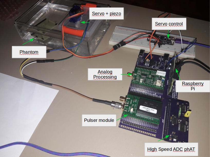
This kit consists of several modules mainly built from easily available components - after a short benchmark of existing ICs. Two electronic modules were specifically designed to provide the basic development kit.
- the Transducer Pulser Module (TPM): designed to provide a precise high-voltage pulse, necessary to excite the sensor, while remaining robust enough to be controlled by an Arduino;
- the Analog Processing Module (APM): designed to correctly process the raw ultrasound electric signal, while easily exposing all intermediary signals, and exposing a digital output to the user
- the RPi high-speed ADC uses two interleaved AD9200, clocked with the RPi, which reads at 11Msps, leading to an effective 22Msps acquisition speed (bottleneck being the RPi copying the ADC values through the GPIOs register to RAM). The signals can be read as is (eg in case of analog enveloppe detection) or offset by Vref/2 (to acquire the raw signal). Due to the GPIO necessary to run the modules, we are left with 2x9 GPIO left, resulting in a 22Msps, 9 bit ADC. One or two logic signals can additionaly be sampled - for an external motor hall sensor for example.
A modular approach was chosen to ensure that each key component inside the ultrasound image processing can easily be replaced and compared with another module. Each electronic module takes the place of a function in the signal processing chain or allows tapping into the different signals circulating between the blocks.
Previous experiments have been done, to get images using different digital acquisition systems, such as a bitscope, a STM32, or a high-speed ADC for beaglebone. The Raspberry Pi was retained in the end for its ease of use, its price, and community working on it - increasing the potential reach of the project.
Assembly guide
Required materials
- A pulser board - to generate the high voltage pulse to use the transducer
- An analog front end - to amplify the weak signals generated by the echoes
- an ADC cape - a custom made 11Msps to 22Msps ADC pHAT for Raspberries.
- a Raspberry Pi, 0 or W to manage everything
- the motherboard, v2 - to connect the different modules together
- and some extras such as headers, jumpers, and a smallish OLED screen
For the transducer, one can use either a ATL mechanical probe for example, or a piezo + servo setup, to mechanically scan the medium to be imaged
Disclaimers
- Disclaimer #0: This is not a medical ultrasound scanner! It's a development kit that can be used for pedagogical and academic purposes - possible immediate use as a non-destructive testing (NDT) tool, for example in metallurgical crack analysis. As in all electronics, be careful.
- Disclaimer #1: though an engineer, this project is the first of its sort, I never did something related. It's all but a finalized product.
- Disclaimer #2: Ultrasound raises questions. In case you build a scanner, use caution and good sense!
General principles of ultrasound imaging
Using echoes to map interfaces
Medical ultrasound is based on the use of high frequency sound to aid in the diagnosis and treatment of patients. Ultrasound frequencies range from 2 MHz to approximately 15 MHz, although even higher frequencies may be used in some situations.
The ultrasound beam originates from mechanical oscillations of numerous crystals in a transducer, which are excited by electrical pulses (piezoelectric effect). The transducer converts one type of energy into another (electrical <--> mechanical/sound).
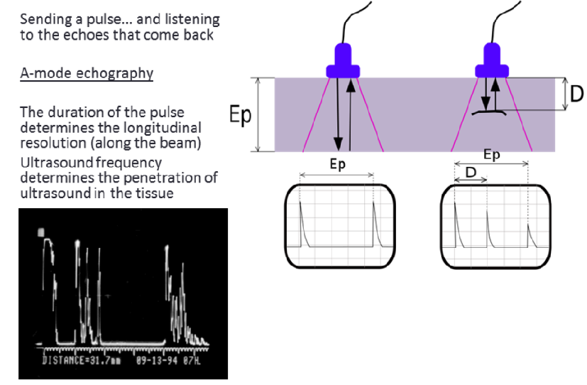
The ultrasound waves (pulses of sound) are sent from the transducer, propagate through different tissues, and then return to the transducer as reflected echoes when crossing an interface. The returned echoes are converted back into electrical impulses by the transducer crystals and are further processed - mostly to extract the enveloppe of the signal, a process that transforms the electrical signal in an image - in order to form the ultrasound image presented on the screen.
Ultrasound waves are reflected at the surfaces between the tissues of different density, the reflection being proportional to the difference in impedance. If the difference in density is increased, the proportion of reflected sound is increased and the proportion of transmitted sound is proportionately decreased.
If the difference in tissue density is very different, then sound is completely reflected, resulting in total acoustic shadowing. Acoustic shadowing is present behind bones, calculi (stones in kidneys, gallbladder, etc.) and air (intestinal gas). Echoes are not produced on the other hand if there is no difference in a tissue or between tissues. Homogenous fluids like blood, bile, urine, contents of simple cysts, ascites and pleural effusion are seen as echo-free structures.
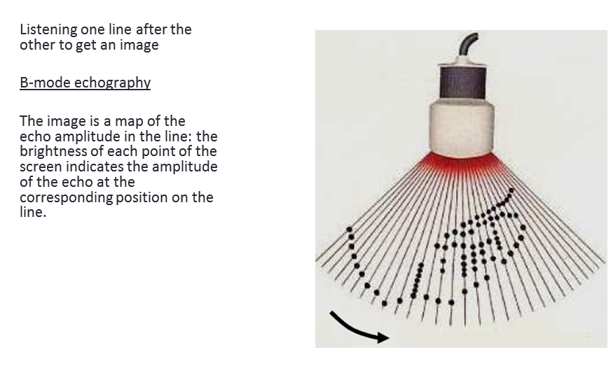
Creating a 2D image
If the process is repeated with the probe sweeping the area to image, one can build a 2D image. In practice, in the setups we'll be discussing, this sweep is done with a transducer coupled to a servo, or using a probe that has an built-in motor to create the sweep.
Experiments
What can be done with this hardware?
This dev kit has been developped for pedagogical purposes, to understand how ultrasound imaging and non-desctrucive testing work. This structure can be used to develop:
- other modalities of ultrasound imaging - and be used as a platform for A-mode, or B-mode imaging;
- it can also be used for array imaging - the modules can be used with a multiplexer for do synthetic aperture beamforming;
- new signal processing methods;
- test transducers - which can be used as well for maintenance and repairs of ultrasound probes;
- other non-destructive testing apparatus.
Why are you doing this ? or besides pedagogical uses of your prototype, we want to know if you are thinking about other applications ? Where your prototype can be more useful? In Africa for example, can your prototype solve some problems?
Benchmark of acquisition
The first acquisition, used as a reference, is through the ADCs of a STM32F205 (feather WICED) - reaching a whooping 1.7Msps (didn't master the interleaved mode..). Even at these speeds, one can see some features of an ultrasound image, on a wire-phantom. However, resolution isn't that great, let's see if that can be improved?
The Raspberry Pi experiment setup
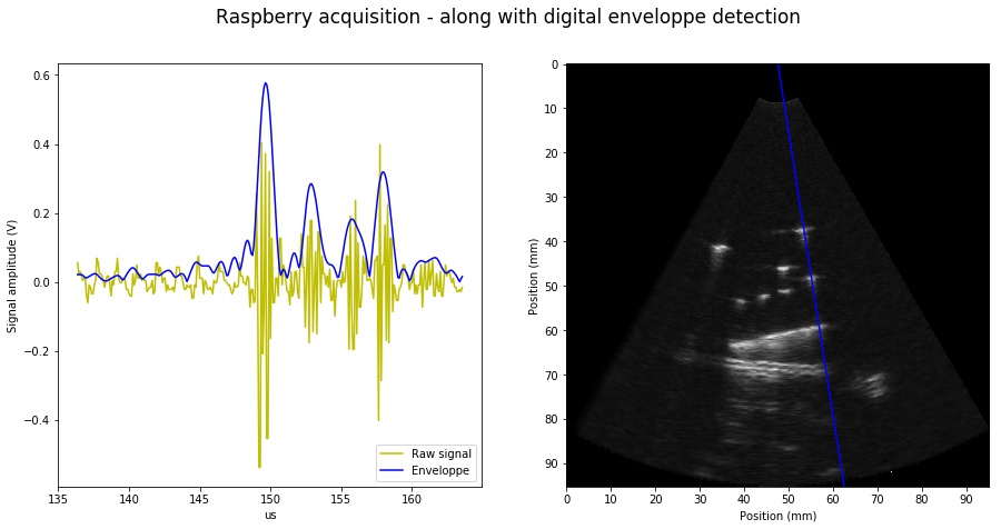
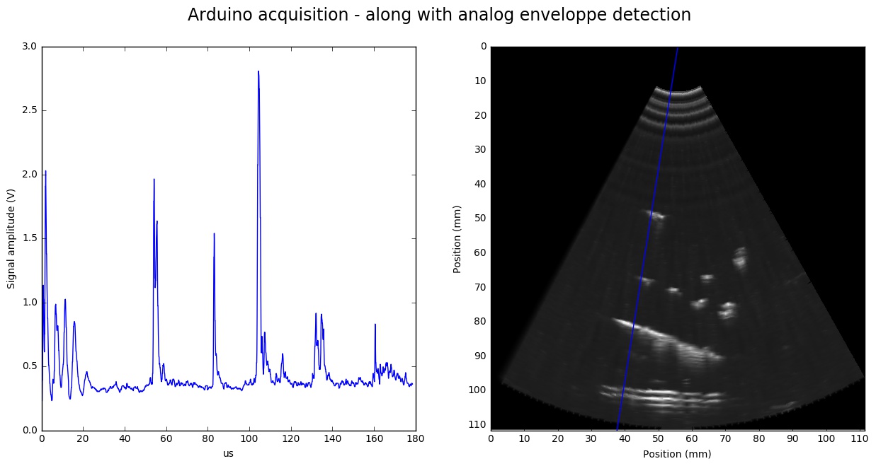
It can be noted that the ADC used in the experiments below is running at half its acquisition speed, due to a blunder - soldering two pins of the second ADC together. However, the 9-bit, 11Msps ADC works relatively well to analyse the raw signal as well as the enveloppe.
This is a picture from a first test with all custom made modules, including raspberry ADC.
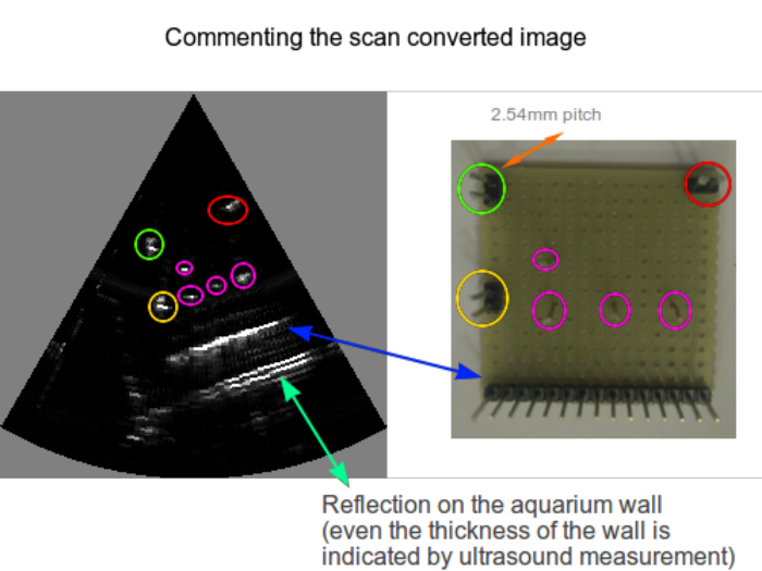
The image is created from a wire phantom, based on a stripboard with a 2.54mm pitch. Wire phantoms are often used as calibration devices, and to assess the lateral and axial resolution of a sensor.
Costs of the materials
Raspberry Dev Kit
Using a simpler linux-enabled controler (the all-powerful Pi in its RPi 0 or Pi W) for the dev kit. Cost of materials aims at being as low as possible, below the 500$.
- Simply the servo and transducer module (cletus) -- get for 80$ (Where? Recycling a transducer from ebay, servo from anywhere (Amazon?))
- The Pi Heart of the echOmods (tomtom) -- get for 10$ (Where? Get the Pi W from plenty of sources)
- Using a dual ADC raspberry pHAT for 20Msps+ acquisition (elmo) -- get for 99$ (Where? OSHPark, MacroFab, Tindie)
- Goblin: a TGC-Envelop-ADC module (goblin) -- get for 149$ (Where? Custom made, get the Gerbers, or buy it preassembled on Tindie, or contact @kelu124)
- Tobo: the HV-pulser (tobo) -- get for 120$ (Where? Custom made, get the Gerbers, buy it preassembled on tindie or contact @kelu124)
Total cost of the set: 458$
Some results: signals and images
I'm getting similar images using the analog enveloppe detection (acquired by the DAQ, through a track exposed on the Analog Processing Module), compared to the digital enveloppe detection, as described below, again on the wire phantom:
The same procedure was applied to acquire the enveloppe created through the analog enveloppe detection, exposed on the Analog Processing Module:
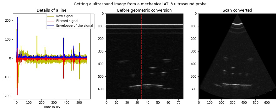
Plugging the Pi to an existing probe
A beaglebone black had been used with its high-speed DAQ to be connected to an existing mechanical probe, with some results. The next step has been to interface the Pi to this probe through the 24Msps Pi ADC pHAT, to see if one can get the same quality of image, and produce a ultrasound loop. The setup looks as below:
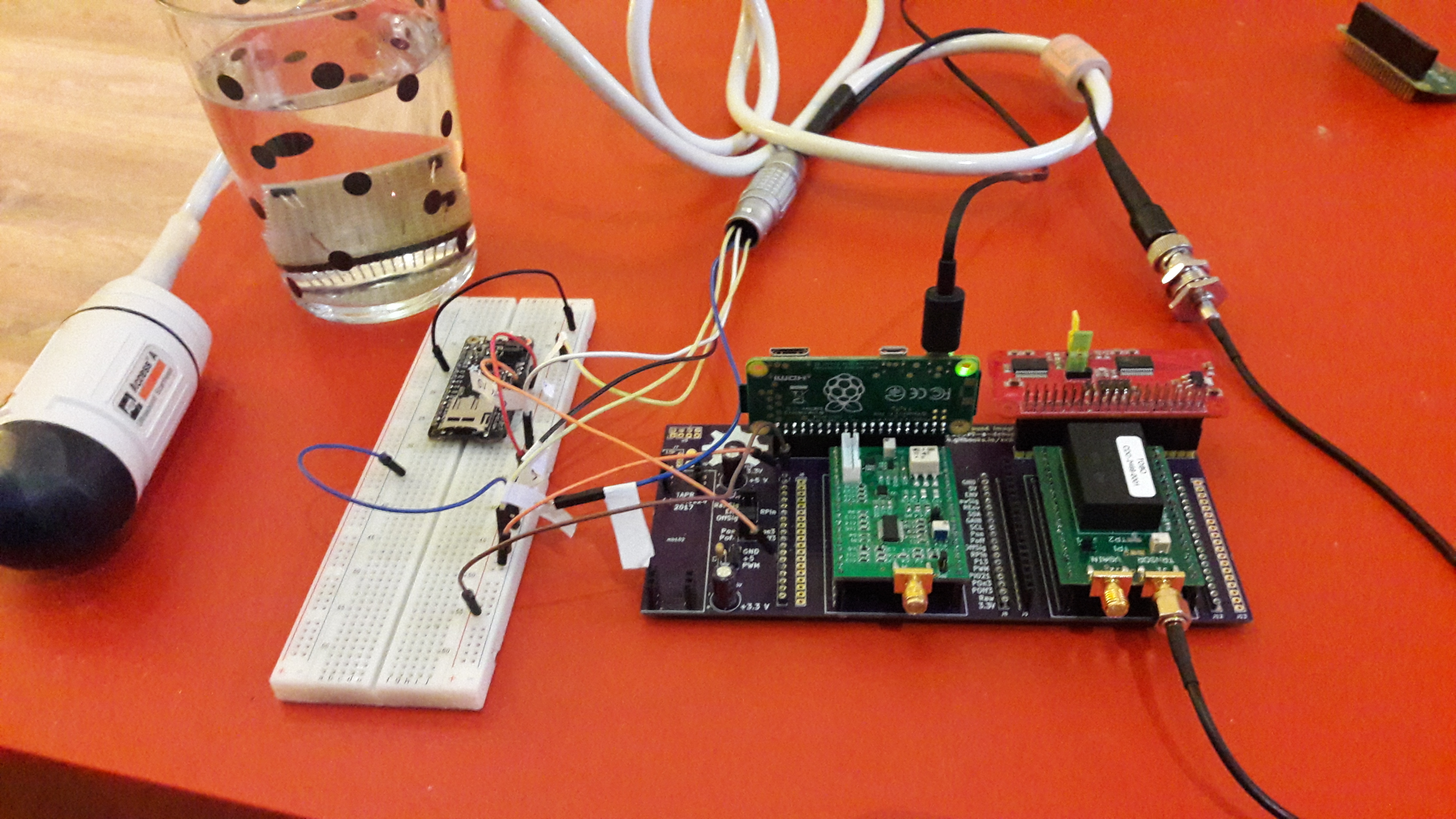
It produced in the end actually good images:
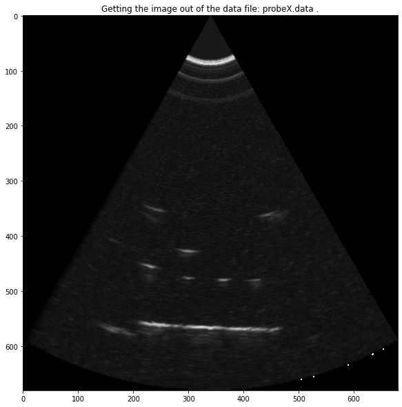
along with details of the processing chain (see the work jupyter notebook):
Lessons on the way
- Start with common elements and modules: I had been quite presumptuous to try and create something from scratch. Do your homeworks, review
- Modular design is the way to go. Discussing in various communities, there are only so many designs that didn't fail in the first time. Make modules out of your designs, so that if one part fails, you aren't left with nothing but a new invoice from the PCBA.
- Share: the world of open-source is awesome. There are plenty of good ideas around, and people don't have the time to implement them. There are other persons who like to implement stuff. Merge the two. Enjoy!
- Do what you like: don't do what you don't like. Find support - even if it's PCBA - for your designs. Sometimes, it's good to rely on pros to do your designs cleanly. Or maybe someone will be happy to review the designs. It does count.
- Document: an easy thing to say.. but it has to be repeated. Don't hesitate to use/make tools to support this quest, it makes your life soooo much easy. All of this gitbook is generated on the fly - my rule of thumb is: Don't write anything twice.
What's next?
On a hardware side:
- The pulser-module design uses only two inputs and one high voltage source. However, the chip enables more complex uses as a pulser, which can be further explored.
- A multiplexer module can be used, to interface this single channel kit with an array probe. Doing this would permit to do synthetic aperture imaging, and to characterize as well each element in the array.
- A whole field left unexplored so far is that of the transducer. As the key sensor in the kit, it would be interesting to explore relevant technologies to develop an open and accessible transducer.
- Quite interestingly, I would love to merge all modules once again on one RaspberryPi3-compatible hat. I want still to cut some costs on the pulser side and increase its robustness.
On a software side:
- The Raspberry Pi can be used a bit more. From a software point of view, the modules could be wirelessly controlled, leveraging the existing wireless communication channel, so that researchers can use a single unit for a laboratory, controlled from personal computers.
- The images will need to be stored in a DICOM-compatible format.
On the OSH side project - the contribution of a tool to the community:
- A campaign should start soon to make the ADC accessible. It seems there's a demand for high speed DAQ there. Just need to confirm the PCBA.
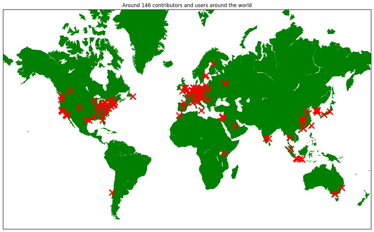
Who's working on this?
A summary of the contributors using the modules (or having ordered them) is detailed below. Some continents are still to be represented!
And you?
Want to learn more? You can join the slack channel if you want to discuss, but there are plenty of other sources:
- Obviously, you can read the online manual/book for a easily readable and searchable archive of the whole work
- You can also fork the project repo, for the source files, raw data and raw experiment logs or explore the hackaday page, where I tried to blog day-to-day experiments in a casual format
- Want a scientific article? Have a look at the article summarizing the experiment on the Journal of Open Hardware - DOI:10.5334/joh.2
- Want to buy the modules and make your own setup? Visit the Tindie store for the analog processing unit and the pulser or the motherboard. Ping me on Slack if there's no stock remaining.
Articles
Under CC-BY-4.0, main article here
Some stats
Some stats
- HSDK: 6900 views, 104 followers, 47 likes
- Murgen: 62200 views, 1600 followers, 269 likes
- ADC cape: 11100 views, 49 followers, 44 likes
- ice40 board: 5300 views, 48 followers, 54 likes
- JOH publication: 12071 views and 1200 downloads.