Tobo: the HV-pulser
What does it look like?
Information
What is it supposed to do?
The aim of this echOmod is to get the HV Pulse done.
How does it work: block diagram

ITF-9_Pon->HV7360ITF-10_Poff->HV7360ITF-2_VDD_5V->R05-100B->HV7360->ITF-mET_TransducerITF-mET_Transducer->ITF-mET_SMAITF-mET_Transducer->ITF-18_Raw
About the module
Pros
- Only needs 5V and 3.3V
- Energy use : TODO
- Using any logic voltage for PulseOn and PulseOff is a pplus
- Can use the potentiometer to control the tension
- Modularity through jumpers and SMA
Cons
Takes a lot of space because of the modularity. SMA, jumpers and pots could be removed.
Little flexibility from the use of ICs.
- There's no impedance matching for the pulser to the transducer, could be better.
Constraint and limits
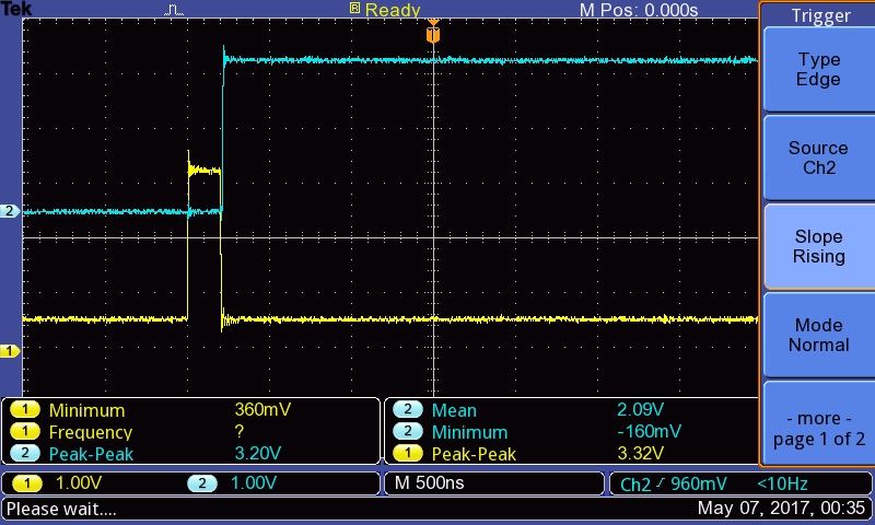
The pulser-control
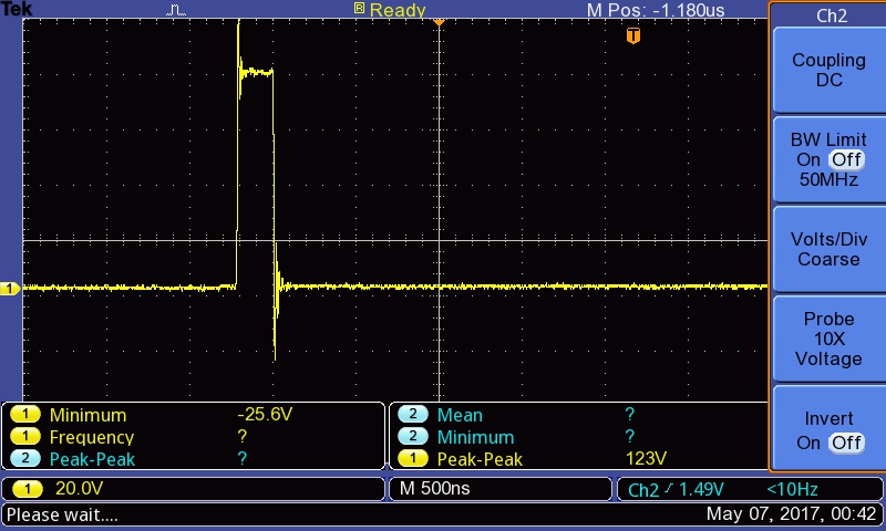
Output signal
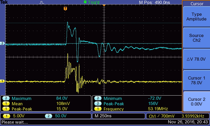
With and without a pulser - no impedance adaptation
Look of the schematics
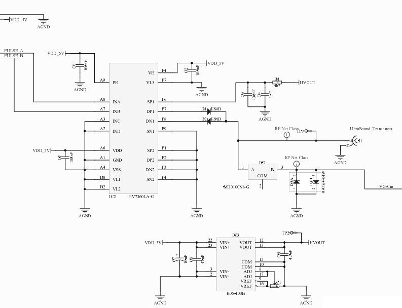
and a link to it (plus some bonus with the map).
Source files include Altium and KiCad - along with the BOM.
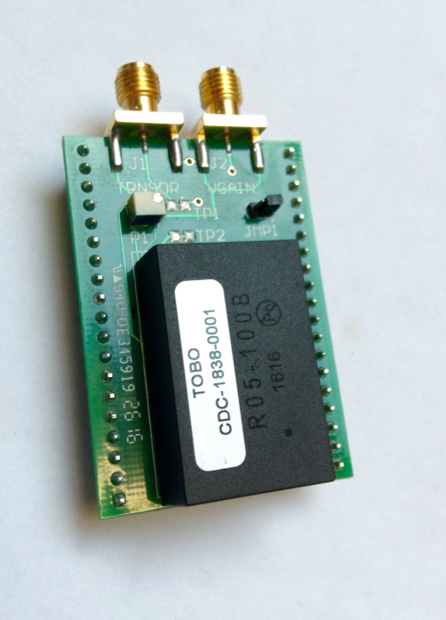
Look of the actual board
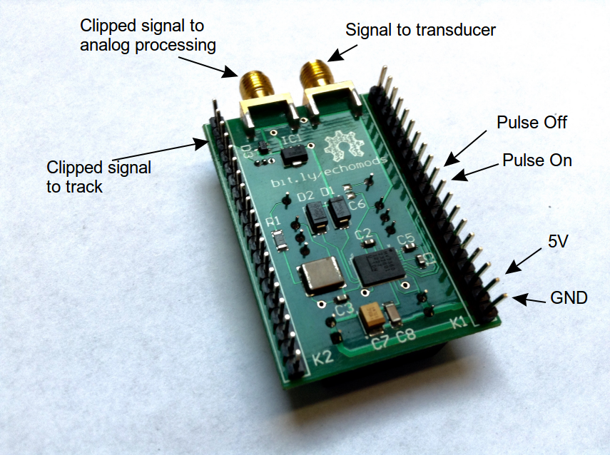
Availability of HV7360
- Some issues with the availability of the
HV7360, living its end of life. The latest version of Altium and Kicad source files should show the new HV7360 CABGA. - However, this latest should be available officially in Jan 2017.
Setting up the module
Setup? Have a look at the quick start guide on how to prepare the pulser.
On the way towards a simpler board
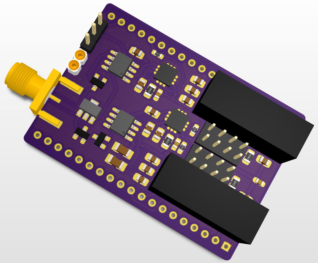
The alt design (and the corresponding the schematics + BOM ).
Discussions
TODO
DONE
- Writing specs
- HV7360 has been updated
- Sending microcircuits to Edgeflex
- Agreeing on the strips/tracks
- Defining the ICs to use to pulse
- Getting schematics
- Publishing schematics
- Receive the module
- Test it with different transducers
- Publish the sources in KiCAD
People
- Sofian (for preparing the field with Murgen)
