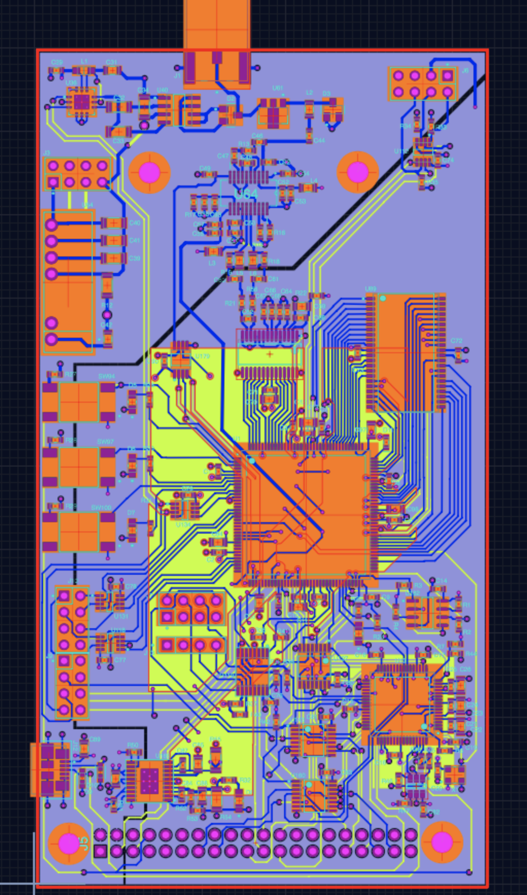
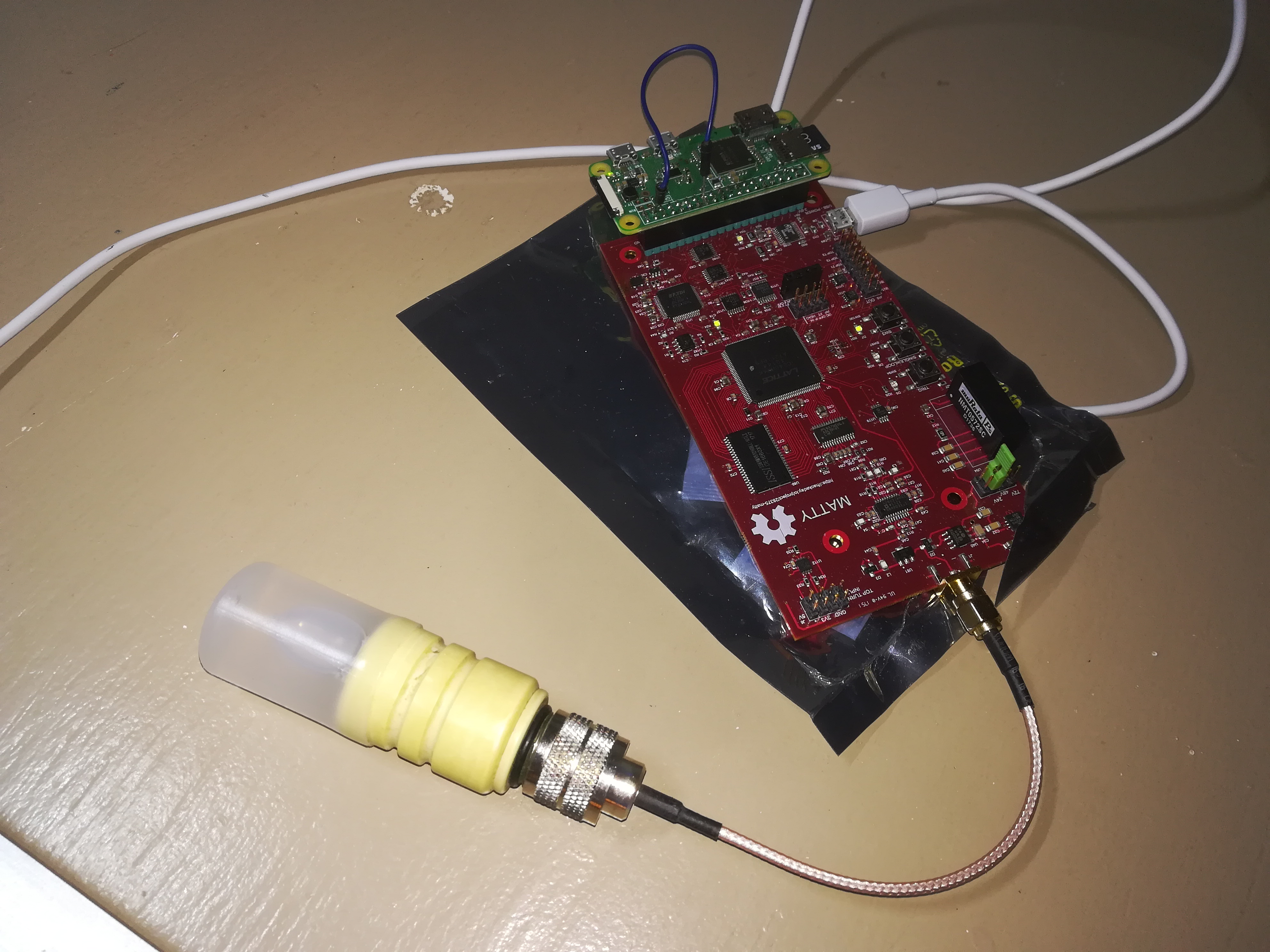
The motherboard of the echomods
What does it look like?
Information
What is it supposed to do?
The aim is to summarize all modules in a all-inclusive board. Fast ADC, good load of memory, good SNR.. the not-so-DIY module, as it comes already assembled with nothing to do =)
How does it work: block diagram
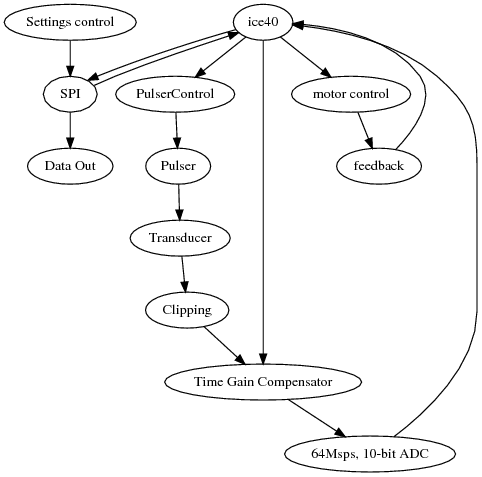
ice40->SPI->Data Outice40->PulserControl->Pulser->TransducerTransducer->Clipping->Time Gain Compensator->64Msps, 10-bit ADC->ice40ice40->Time Gain Compensatorice40->motor control->feedback->ice40Settings control->SPI->ice40
About the module
Pros
- All inclusive!
- Cost effective
Cons
- v1.0 has still some issues
Constraint and limits
v1.0: Initial design
- Some issues are left, need to take care of as in next steps
- Interesting first result, summarized below:
Getting images from a retroATL3 probe.
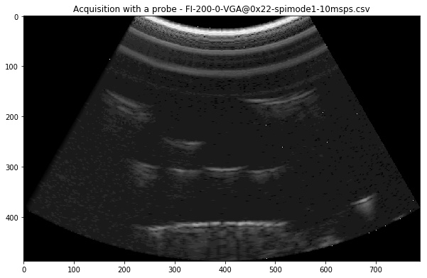
(see the readme )
Setup
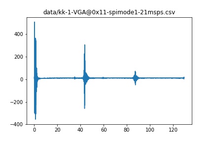
Results
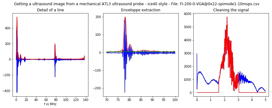
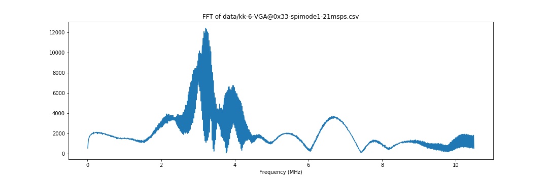
Fooling around
Extracting spectrum analysis of this line
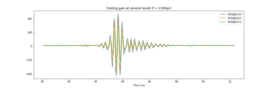
Playing with the gain setting
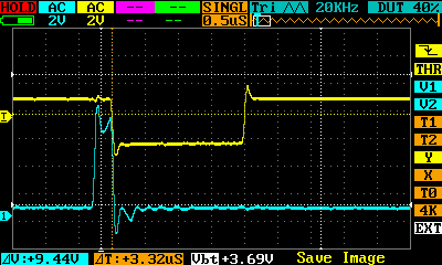
Controling the pulser works!
- Checked here
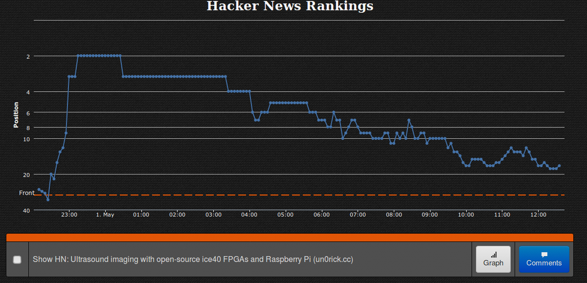
Reaching n2 rank on HackerNews
On may 1st =)
Discussions
TODO
- See the next steps
- Having it work with a retroATL3
DONE
- Getting some signals!
People
- Kelu124