-> a blog
Will's system
Exchanges
2017-04-13
Thought I'd drop you an email since I have some oscilloscope screenshots to share.
I will definitely publish my results and hardware documentation on github and hackaday. The main reason why I haven't been documenting as I go is simply because I am stretched for time, so everything is going into a rough workbook. I'll have to check if it's okay to publish my thesis upon completion, but I don't imagine it'll be a problem for the university.
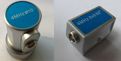
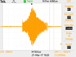
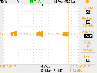
Quite impressed with those plots! What is the large pulse at the start, is it related to the transmission or is it a reflection? I was thinking of getting the LTC5507 as it is smaller and stocked by a local supplier, but the ADL5511 seems to have a much more linear output, so I'll definitely use it instead of the cheaper option. I've decided I'll include the HV7360, because it'll make it much easier to compare different waveforms. I don't think I'll attempt any impedance matching to the transducer. I would use a smith chart, but I actually haven't been able to determine the characteristics of either of my sensors. In fact, I've attached some strange plots I got of how the transducers respond to a simple 1V pk-pk 3-5MHz sine sweep. My rectangular transducer favours higher frequencies, but didn't appear to actually resonate at any point, while the cylindrical one resonates at exactly 4MHz and rolls off at either extreme. Both tests were conducted simply by plugging a BNC splitter into a signal generator and attaching both the transducer and oscilloscope. If you happen to have some rough values for an electrical model (I would be extremely grateful!) you can easily use a smith chart online or on paper to calculate the matching network required.
Finally, I was curious about your choice of components for the receiver side. Did you choose the AD8331 and then choose a differential op-amp as a consequence, or is there a specific reason you used a differential op-amp? I don't have a great deal of experience in the area of amplifier design. Are there any special requirements to the balun transformer? Sorry to level so many questions at you, it's exciting to have a design to sanity check against before I send my own board off in the next few days.
2017-04-14
Took a look at the resources at the bottom of the page you linked (http://www.biosono.com/PrmtLgd/PrmtLgd.php?id=TrnsRlc , http://alejandria.ccm.itesm.mx/biblioteca/digital/liele/pcmc.pdf, and impedance matching https://www.ncbi.nlm.nih.gov/pubmed/23443705 ). One of them has a calculator, very helpful! The only value I don't know is 'Kt', but the small sheet that came with it had a value for that if I recall correctly. The values it calculates seem pretty reasonable and the frequency response I got was close-ish to what I measured in the lab. Might not be too hard to impedance match after all.
Voltage is generated through buck/boost converters. Inconveniently, I'll need 1 at about +/- 16V (it may be easier to supply my board with +/-16 V directly with the lab equipment) and another at 100V, such as the one you've used, although it is quite large. I currently have 2 DC-DC converters and 3 linear regulators (2 for the FPGA), which is a little excessive. I am considering moving the FPGA entirely off board and using a dev board for that instead. Saves about 25% on space and removes 2 of the regulators.
Did you have to make your own footprint and symbol in altium for the HV7360? I haven't yet found one online.
The pulse size is long as a consequence of pulse compression. It works very well for targets that are far away (Radar systems and sonar) but is difficult in Ultrasound due to having a minimum distance associated with its pulse width. The current pulse length under nominal conditions is 214us, which can only be shortened by raising the clock rate of my FPGA (easy) and by raising the effective sampling rate of the DAC (less easy, but still viable). For demonstration purposes, I expect the university will be okay with me providing an 'inverted' phantom with obstacles present in open air which are close together, similarly to your prototype board with bits of metal sticking up. I strongly suspect I will get poor preformance placing the transducer less than a few inches from the objects, but that is a consequence of the pulse. I imagine the viability of different types of pulses and modulation will be something I can only assess right at the end of, or after the project.
2017-04-19
I would be happy to provide the plans for impedance matching at completion, though I don't know if my own board will use it as I need to send my board plans off asap, so they're very basic. It'll likely be the sort of thing I calculate and simulate for the report.
I would be thrilled to assist you with the project, though I may not be truly free with my time until much later in the year.
I've actually got two boards for my presentation, one of which has a higher slew rate and sampling rate, while the other is based off your design for both benchmarking and testing PWM with the HV6370 in case I cannot get the sinusoid board to work very well. So that may be something you'll be interested in.
One thing that still sticks out to me is how expensive and large the 100V converter is. That may be worthwhile investigating for lowering the cost. Otherwise the components all seemed reasonable. I know there are special ICs for generating 220V which are small and cheap, but there doesn't seem to be many for the ~100V range.
One thing I'm still curious about is the C4 1nF capacitor. Is it selected for its voltage rating or does it pass a lot of current due to ripples from the converter? Also, I see a lot of 120uH inductors between different stages of the amplifier. Are they to suppress high frequency harmonics?
2017-04-21
I am going to add the impedance matching just before the transducer with a zero ohm resistor in parallel that can be soldered in to bypass it if it doesn't work as intended.
What are the MAX2709? I can't seem to find any info on that part.
My major motivation for producing two boards is to minimise the potential problems I may have with ground bounce and noise in the ground plane. From what I've read, the approach of using vias between ground planes to shield low power sections of the board is best practice, but I worry because my ground plane for the LNA and other sensitive components is shared by the DC-DC converter. However, your ADC board actually seems to share the ground connects as well, so it mustn't be a big issue. Do you see any noise when you probe test point 10? How does switching caused by the HV7360 affect the ground plane? I haven't had a great deal of experience dealing with ground plane issues,so I may be overreacting.
I definitely would not apply 220V to the piezos, not only will it probably damage them but it's also unsafe to handle something that is operating at that kind of voltage. I was simply looking at other ICs. I am skeptical of using a 555 and a voltage doubler/tripler/etc. It sounds delightfully simple but I don't believe those setups will be able to provide enough current at the output, and their voltage will drop heavily at the moment the transducer is switched in, so they would be unsuitable for short pulses, at least as far as I can imagine.
Finally, yes I was referring to the cpacitors around the pulser. I'll stay on the safe side and use a similar size. I don't want to risk having a passive component blow up and then not having enough space to solder in a larger one.
2017-04-30
I don't know a great deal about the Piezos I am using, I found them on Aliexpress where they are sold as 4MHz replacement parts for a flaw detection sensor, which probably means they are operated with a pulse train of around 250ns each. The 200us pulse I was supplying was a sine sweep to satisfy the pulse compression algorithm. I have not yet tried applying a short DC pulse, but in terms of range resolution I should have a roughly equivalent performance between a 300ns pulse and a ~200us 2MHz bandwidth sweep. This is neglecting a lot of conditions like power and minimum range. I expect to have some issues with ringing due to not having any special devices to compensate (other than diodes). Indeed, if my transducers ring for 200us afterwards as well, that would be a big issue.
I just got my board a few days ago and finished assembly today. I didn't have time to produce a second board with your parts for bench marking so I've attached a photo of my own (pin headers and a few components missing). The major differences between our boards is: 1) Operating at 36V peak to peak with a maximum current of around 300mA. I've yet to find out if this will damage the transducer. 2) Arbitrary waveform input (through a DAC), with enough slew rate to apply short DC impulses similar to yours. 3) Lack of envelope detection. I'm instead sampling the received waveform directly and re-constructing it on a computer.
The general flow of my board is as follows:
- 100 MHz data and clock comes from a very close FPGA that has sine tables or timings for other waveforms
- DAC908E produces a 3-5MHz sine sweep or DC impulse
- ADA4870 amplifies the DAC output to +/- 18V, fixed gain
- Diode bridges and MD0100 isolate the transmit and return path from each other, transducer is connected before the MD0100
- Optional second BNC terminal can be used to connect a second transducer for receiving only, if the appropriate jumpers are connected (0 ohm resistors)
- AD8330 with trim pot amplifies the signal to within 0-2V (this is not a very elegant solution)
- ADA4930-1 drives the ADC, it was a case of following the datasheet for this one, so I hope it works. It also has the worst possible package to solder, 3x3mm QFN16.
- Transformer Balun, followed by a AD9200 ADC that can be externally clocked, but appears to prefer about 20MSPS.
I'm running into data throughput issues with my setup, because the 20MSPS ADC is connected to an FPGA which then needs to divide up the signal and strip out dead-time to make it suitable for a low bitrate link to the computer. In hindsight, a microcontroller would have been better for this reason. My supervisor has provided me with a few methods to reconstruct the reflected waveform from limited sampling rate, but the lack of an envelope detector may introduce some errors. I'll have to see how I go in that regard. I may end up attaching an envelope detector near the output anyway.
I actually haven't yet been able to do my preliminary performance tests, because for some strange reason the DAC is drawing half an amp at 3.3V and quickly overheats. I suspect it may already be dead for this reason, but it actually still works correctly when I turn off the power and connect the data and clock pins normally. This is by far the strangest thing I've seen so far in my degree, as it even outputs it's full rated +/- 1V. However, due to drawing power from (presumably) the data and clock lines, the output is very distorted. This could also just be a case of me connecting the data bus backwards, I've done that a few times already. For the moment, I may need to run it in this state and deal with the fact it's sending garbage to the transducer, because I need to make sure nothing else on the board is faulty. I suppose I'll then replace the chip or replace the DAC entirely with an R/2R resistor ladder, which actually worked fine previously.
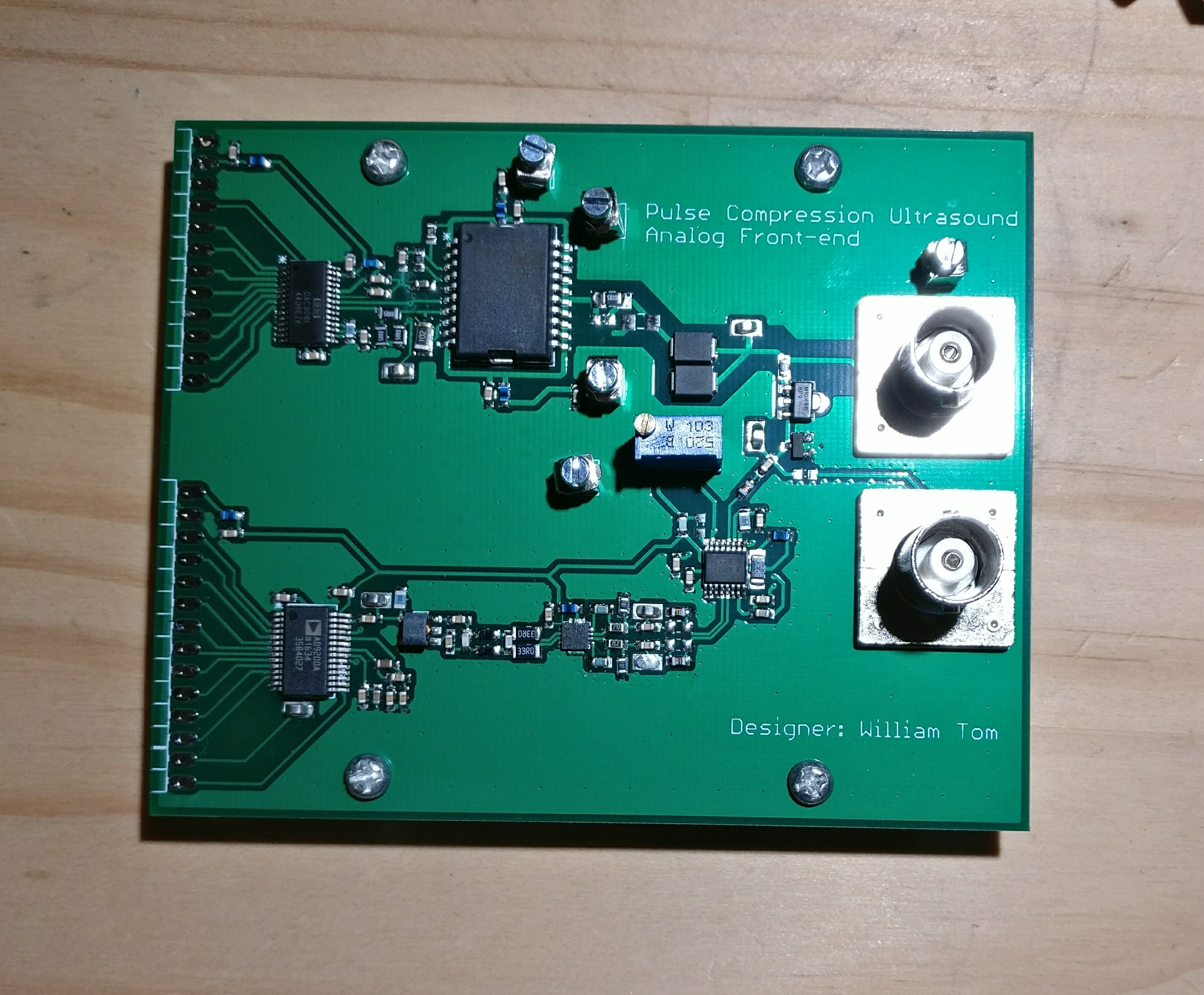
I am hopeful that the DAC (top left) is the only dodgy component, potentially killed by my hot air gun. If other things are also broken, that could prove quite inconvenient this late into the project. As always, I greatly appreciate your ongoing documentation of your project. Do you happen to have any full sets of data from the ADC when looking at a real object? I suppose if I can't get my board to function correctly the next best thing I can do is get sample data to compare the simulations to.
I wanted to have more good news, but unfortunately progress at my end is as slow as ever. Also! I did the calculations on the impedance of the part with the information I had available, and it looks like my transducers have a very low capacitive reactance (relative to the resistance) so there isn't much point in impedance matching to them. I don't know if this is a general case, or specific to these transducers. It also depends on the thickness of the piezo material, which I had to estimate.
p.s. Board is 2-layers, very affordable but a pain to route, those screw terminals are for external power supplies.
Context
Exchanging on boards after meeting on HAD =)