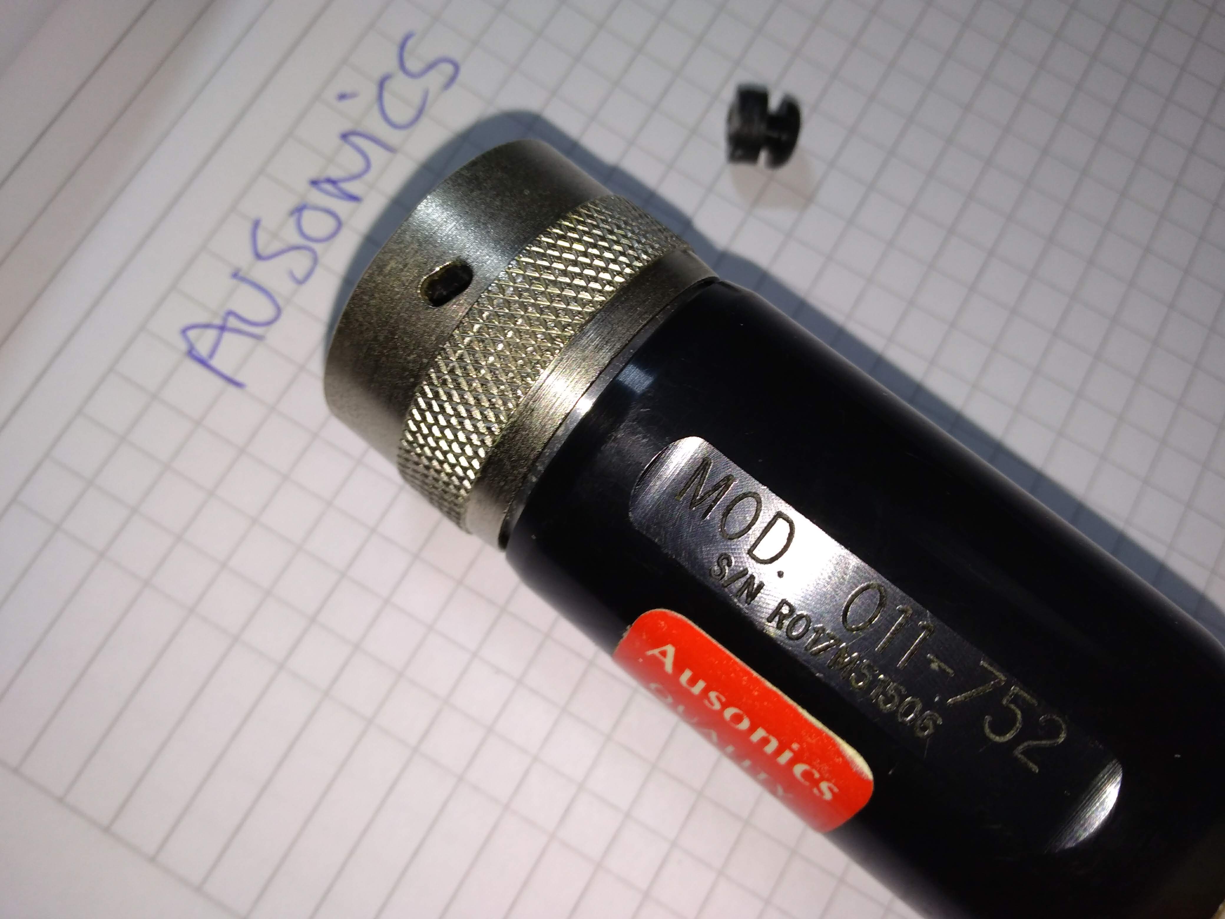
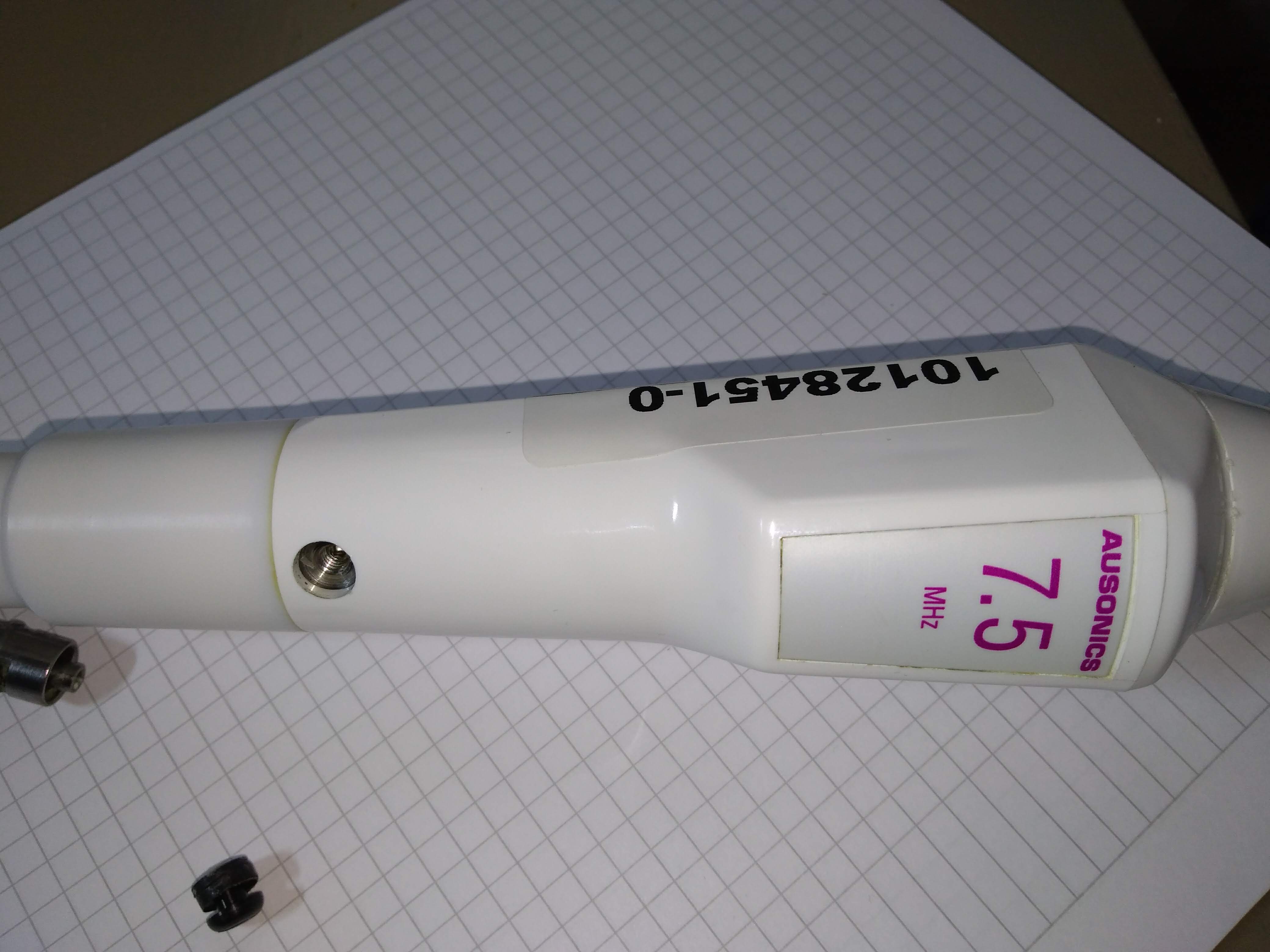
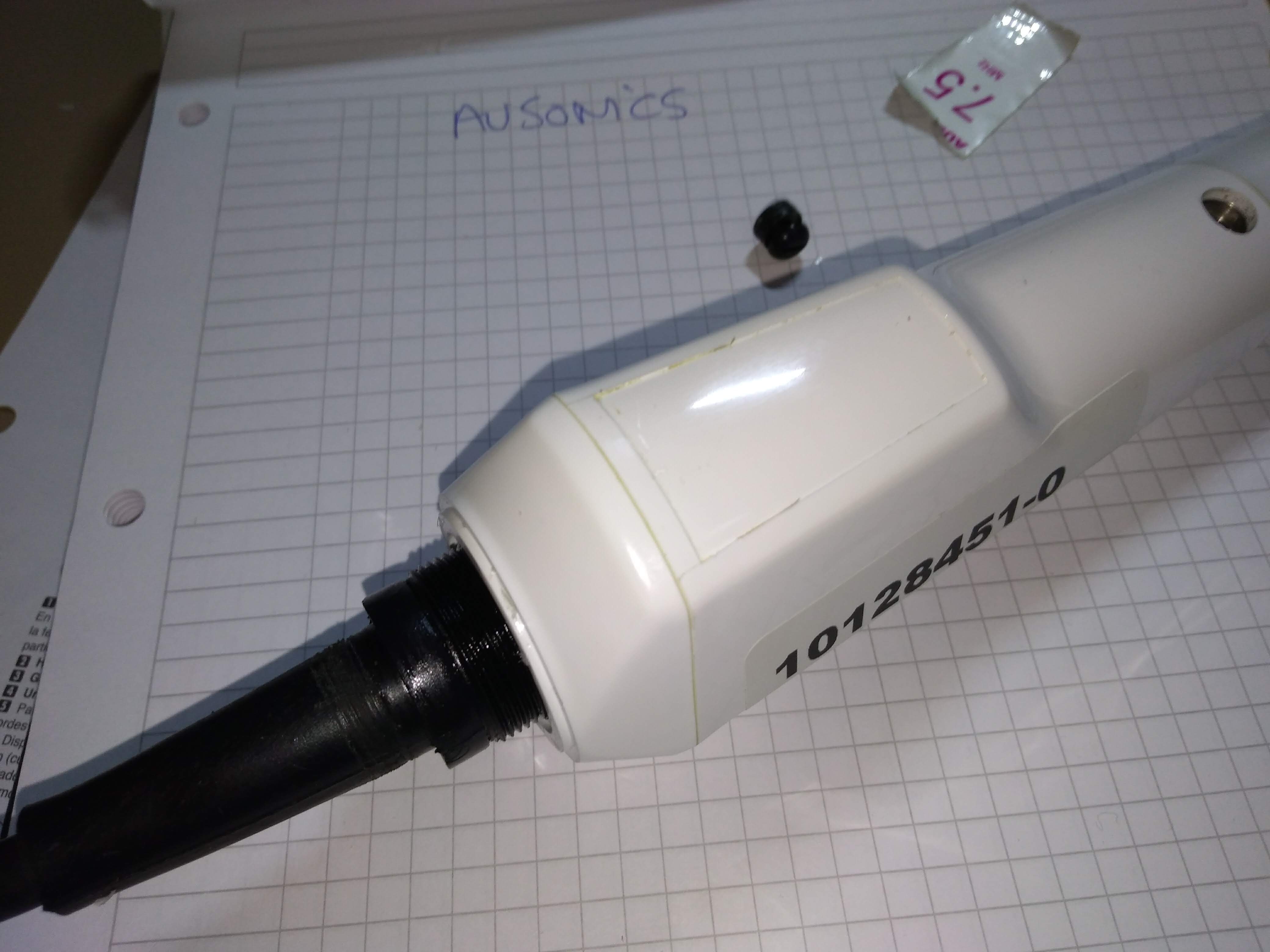
Getting in a Ausonics 7.5MHz probe - 20180809b
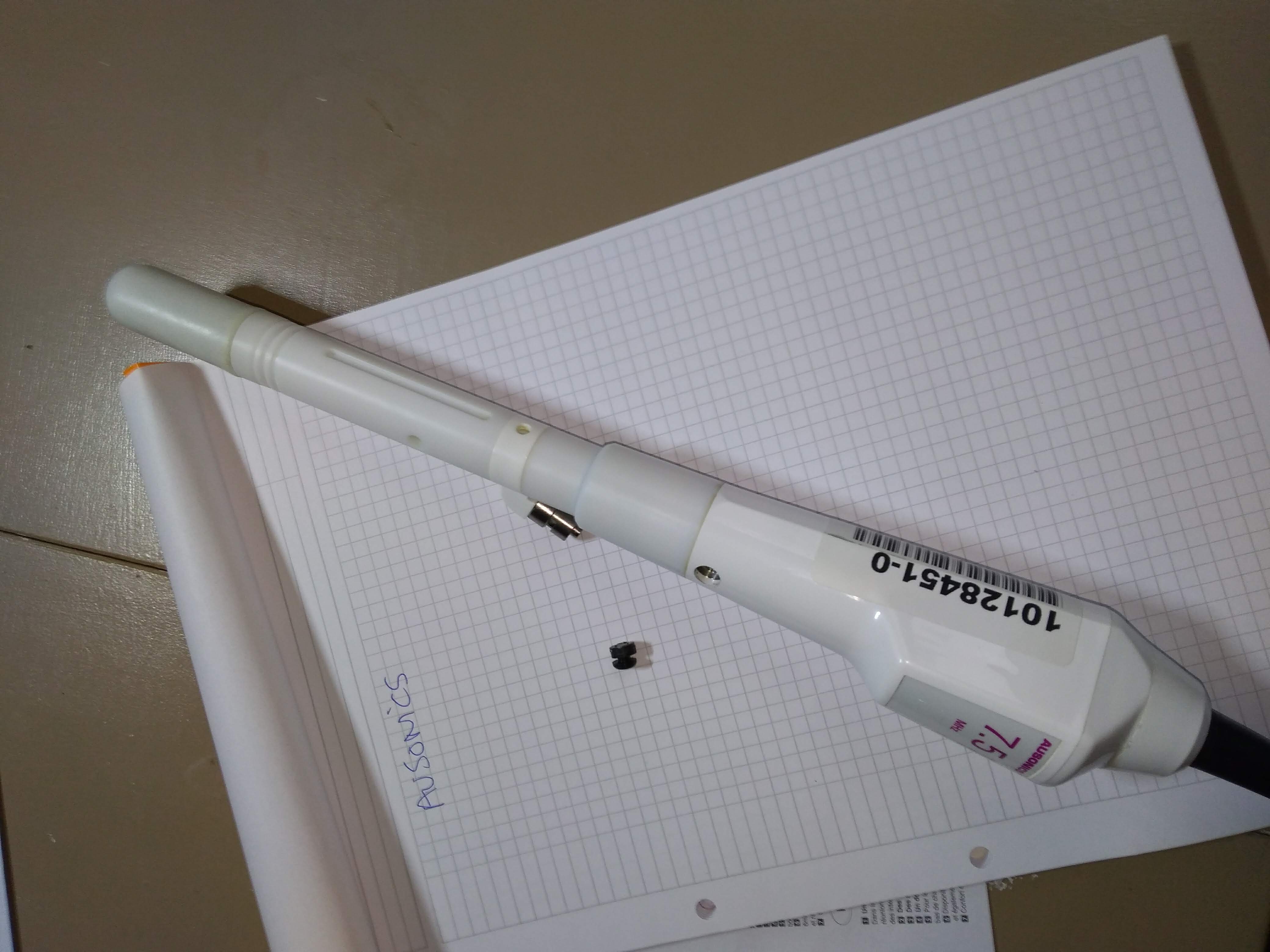
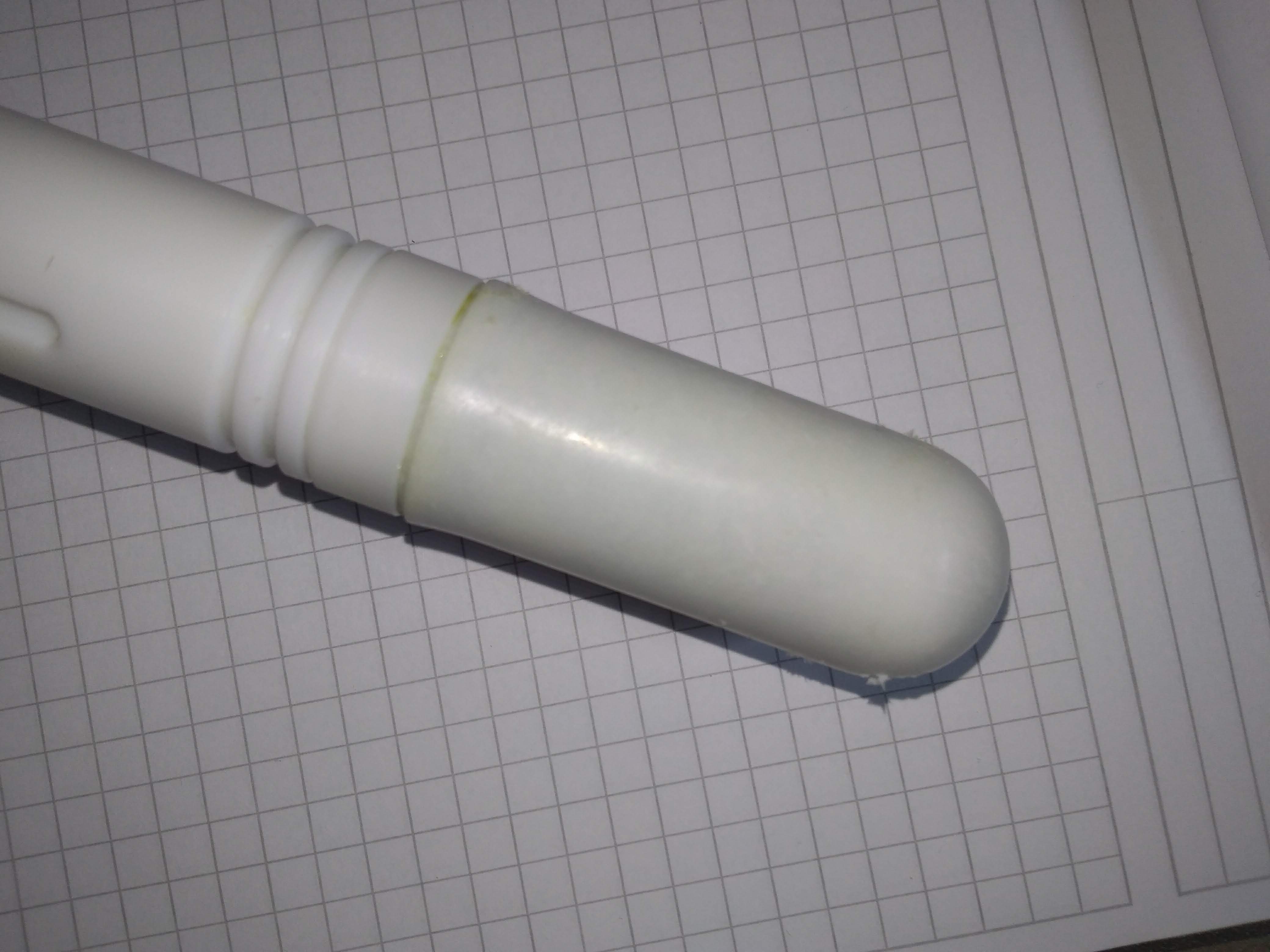
First view: seems to be an intracavity probe as usual.
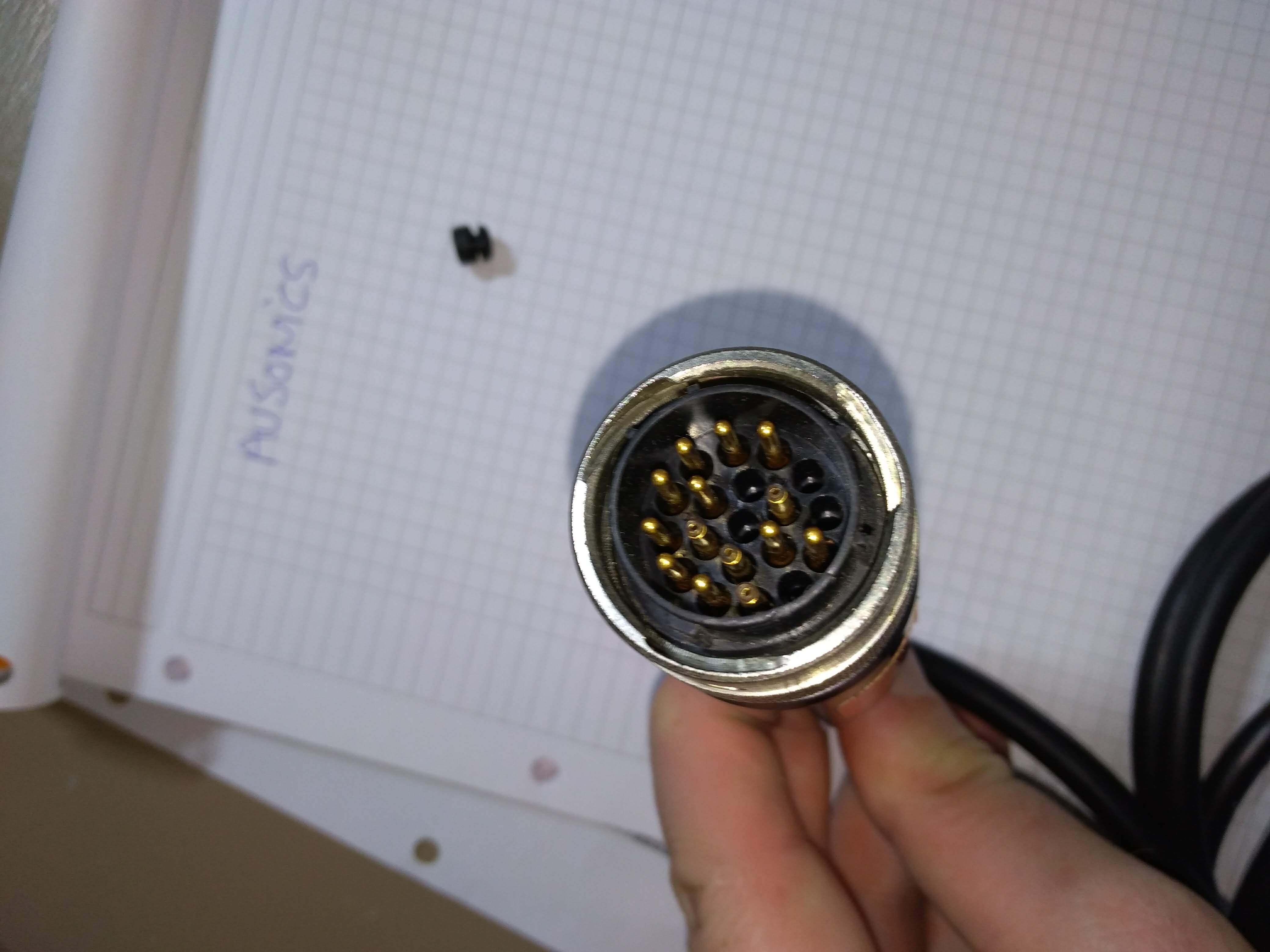
- Connector, a bit big, hints at 4 coax, and 10 pins as usual.
- 4 channels of analog, 10 analog ?
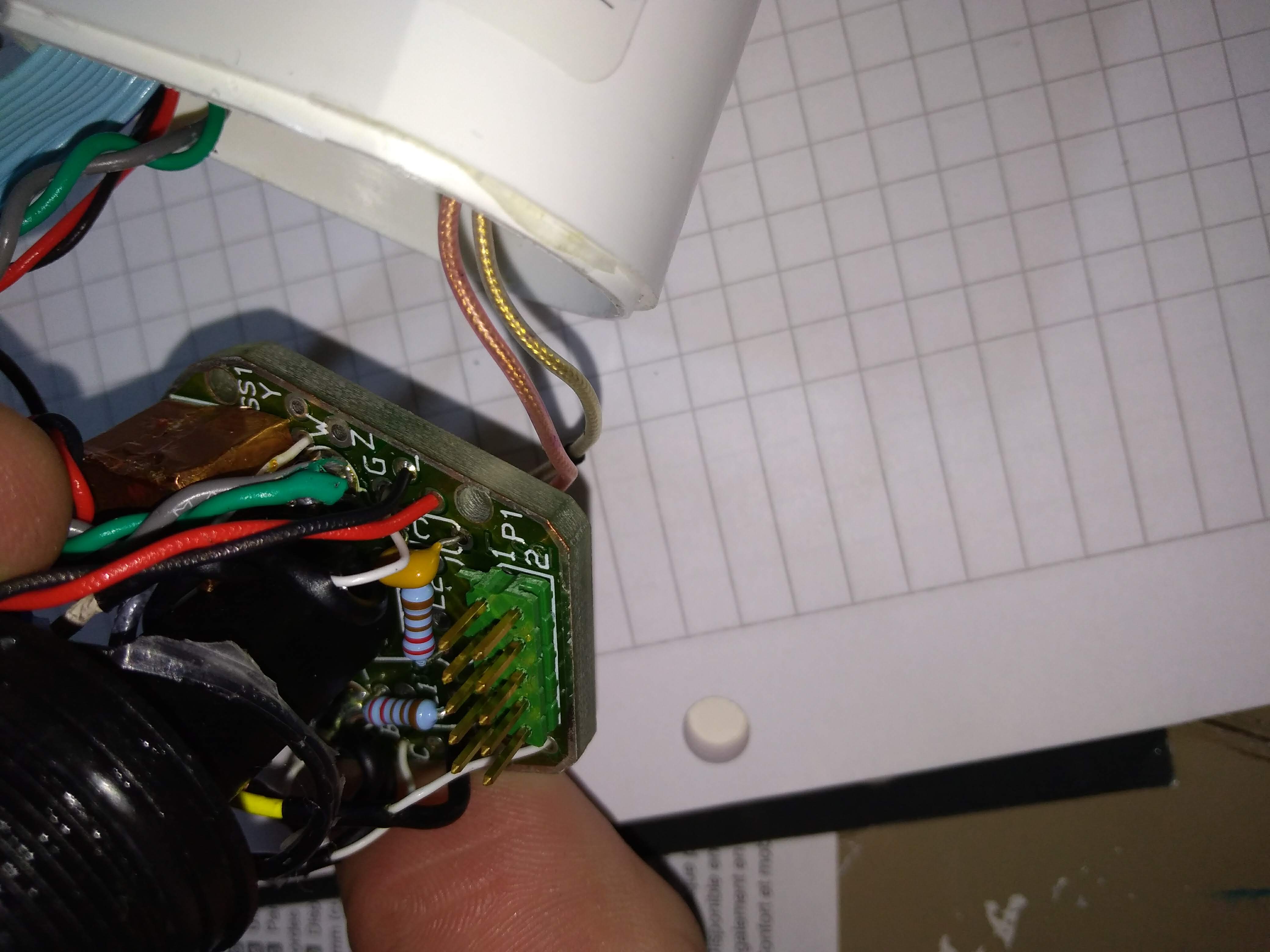
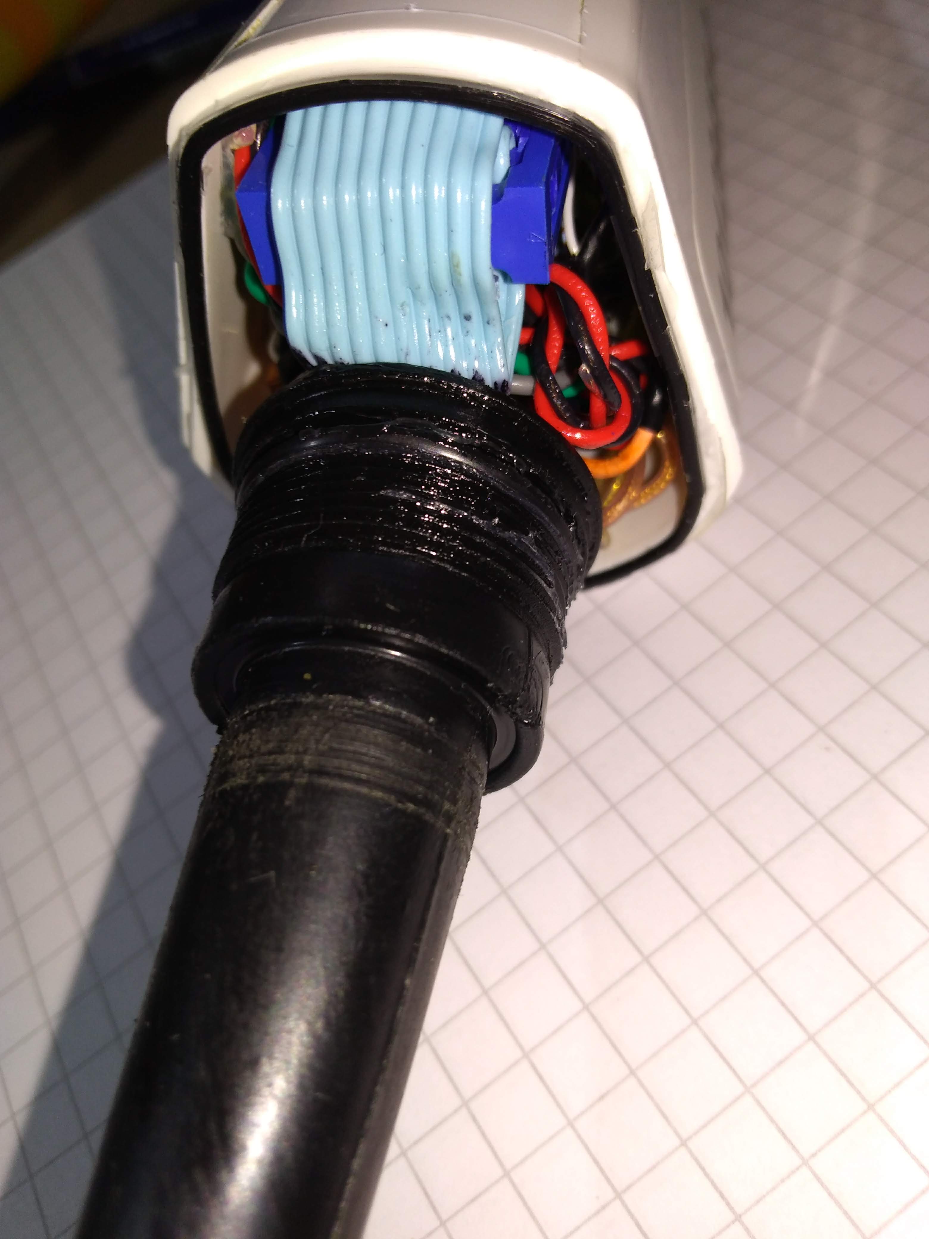
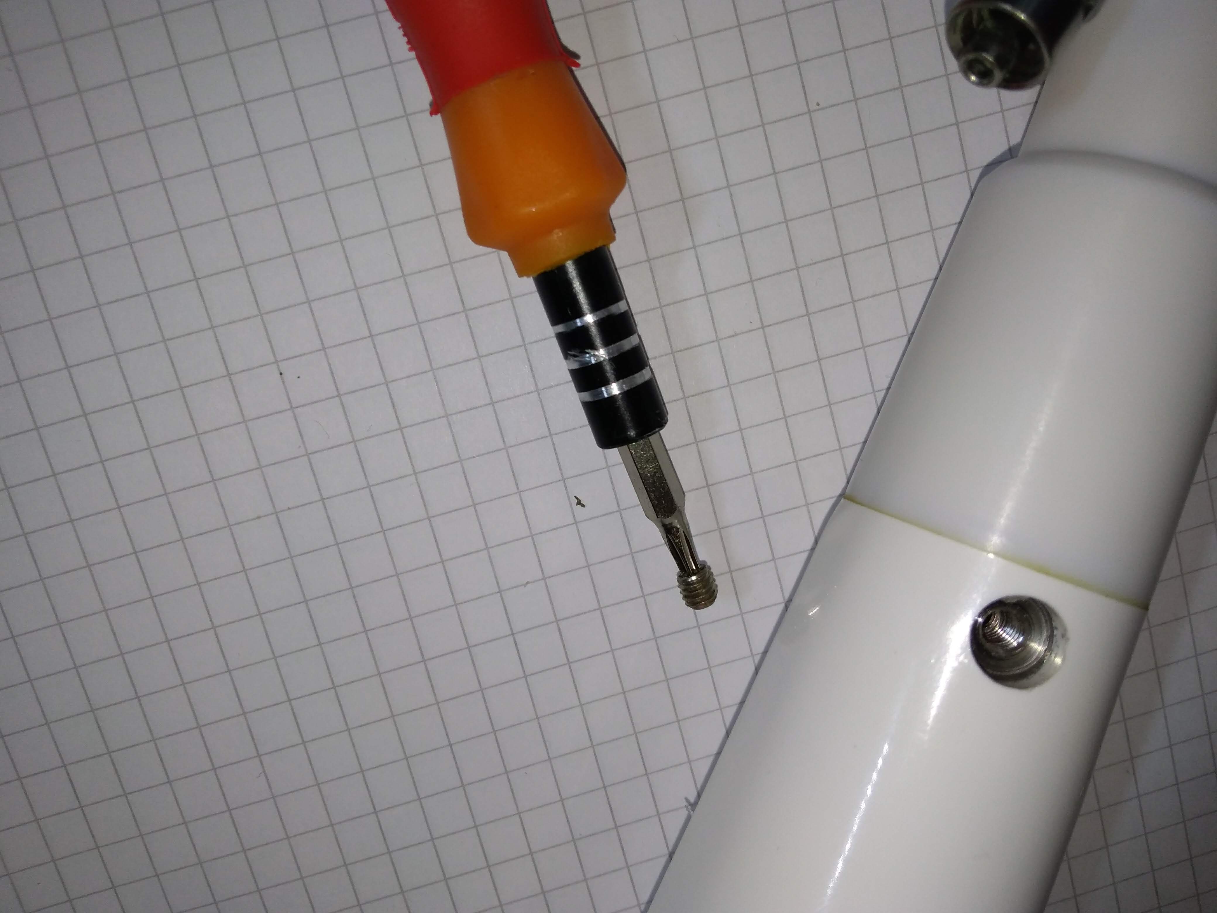
A bit tricky to open, but back unscrews, then the plate gets removed.
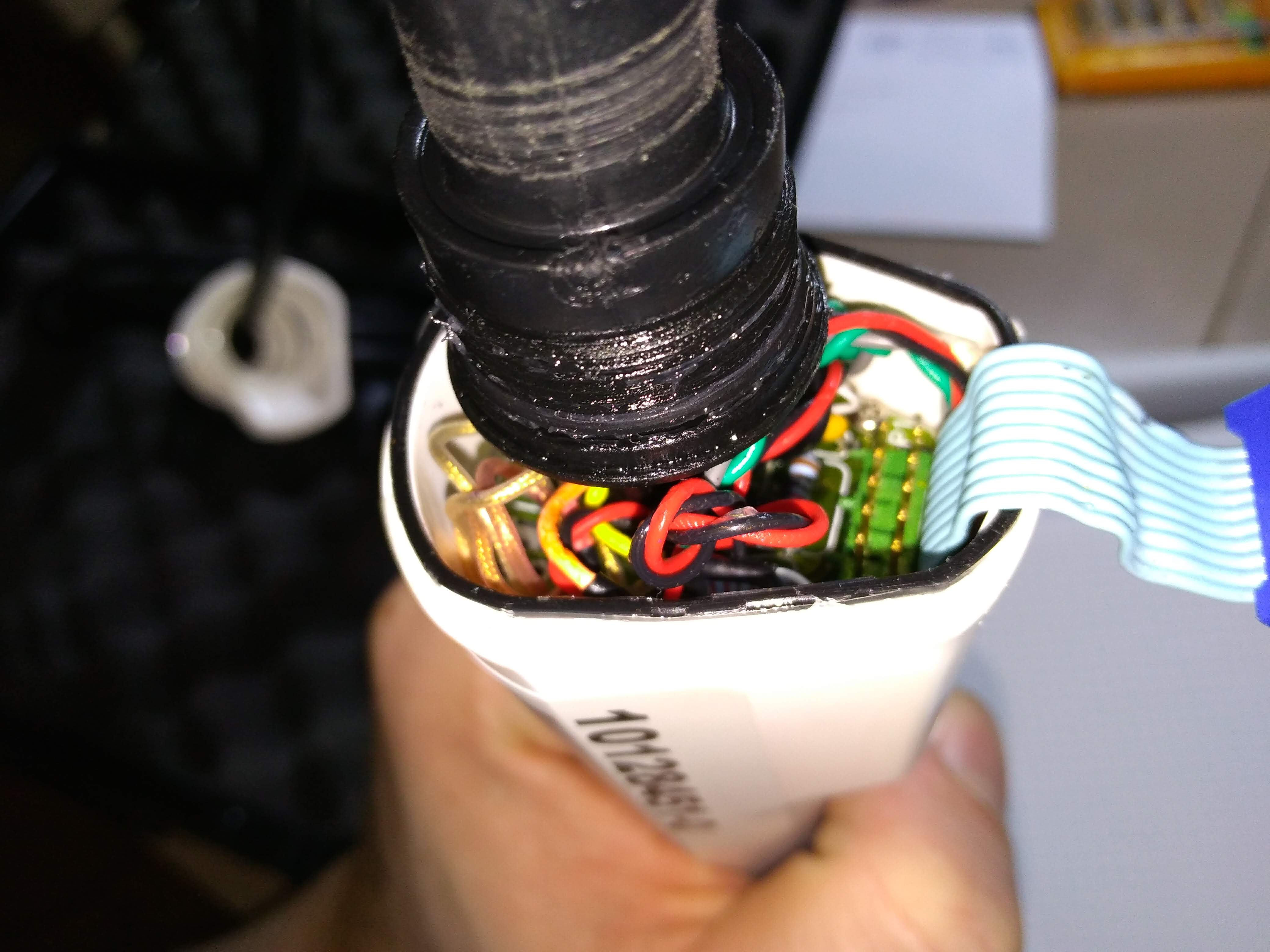
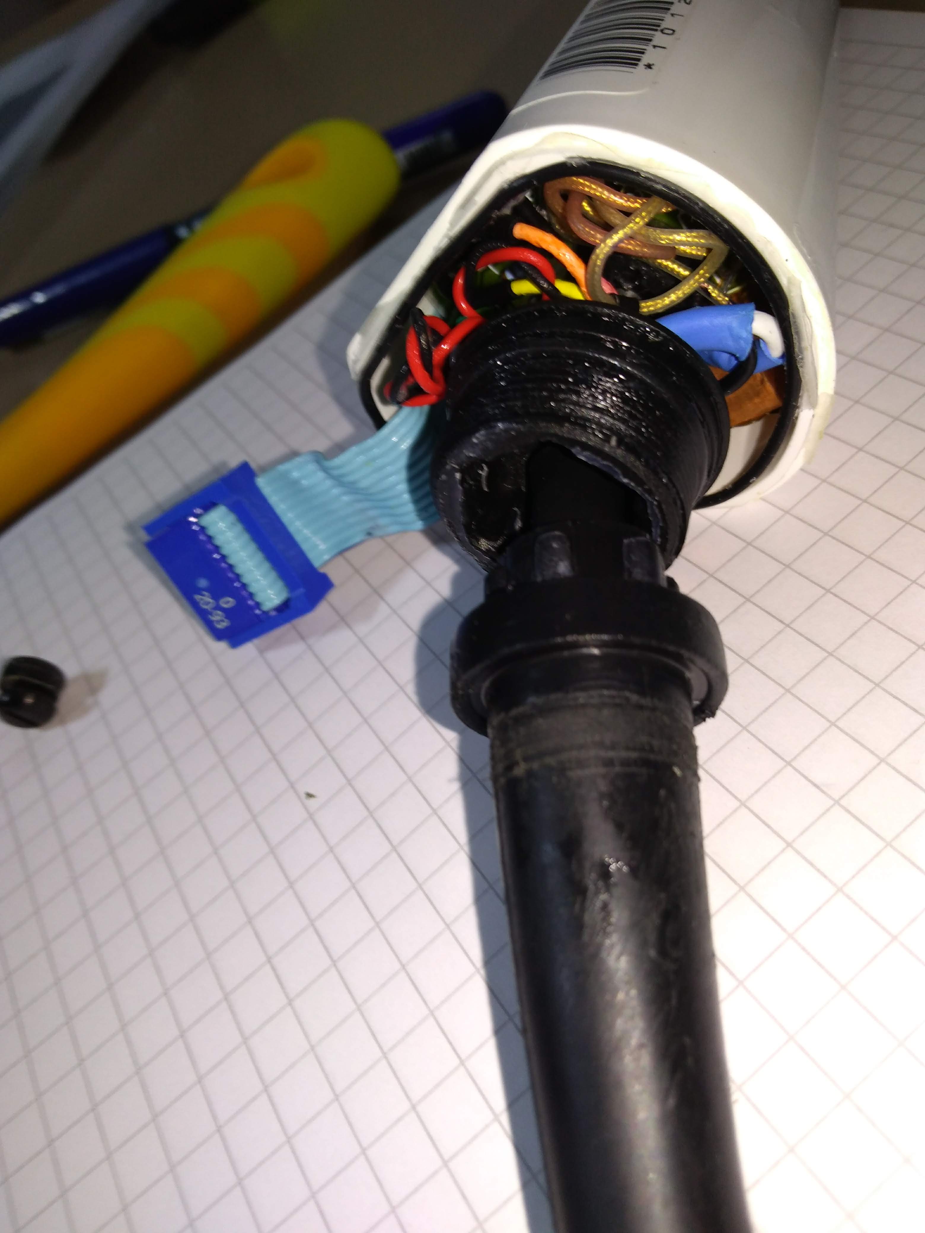
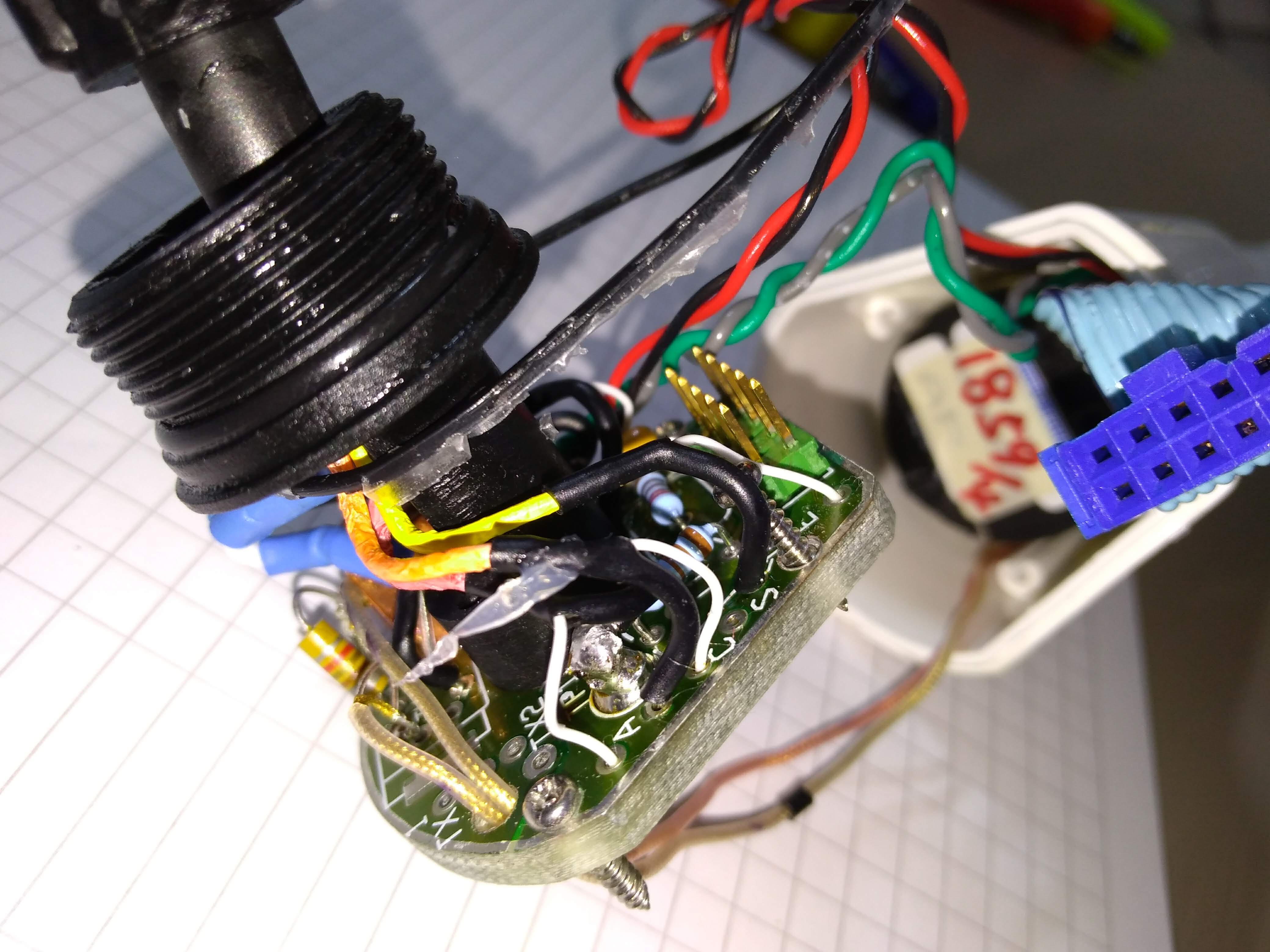
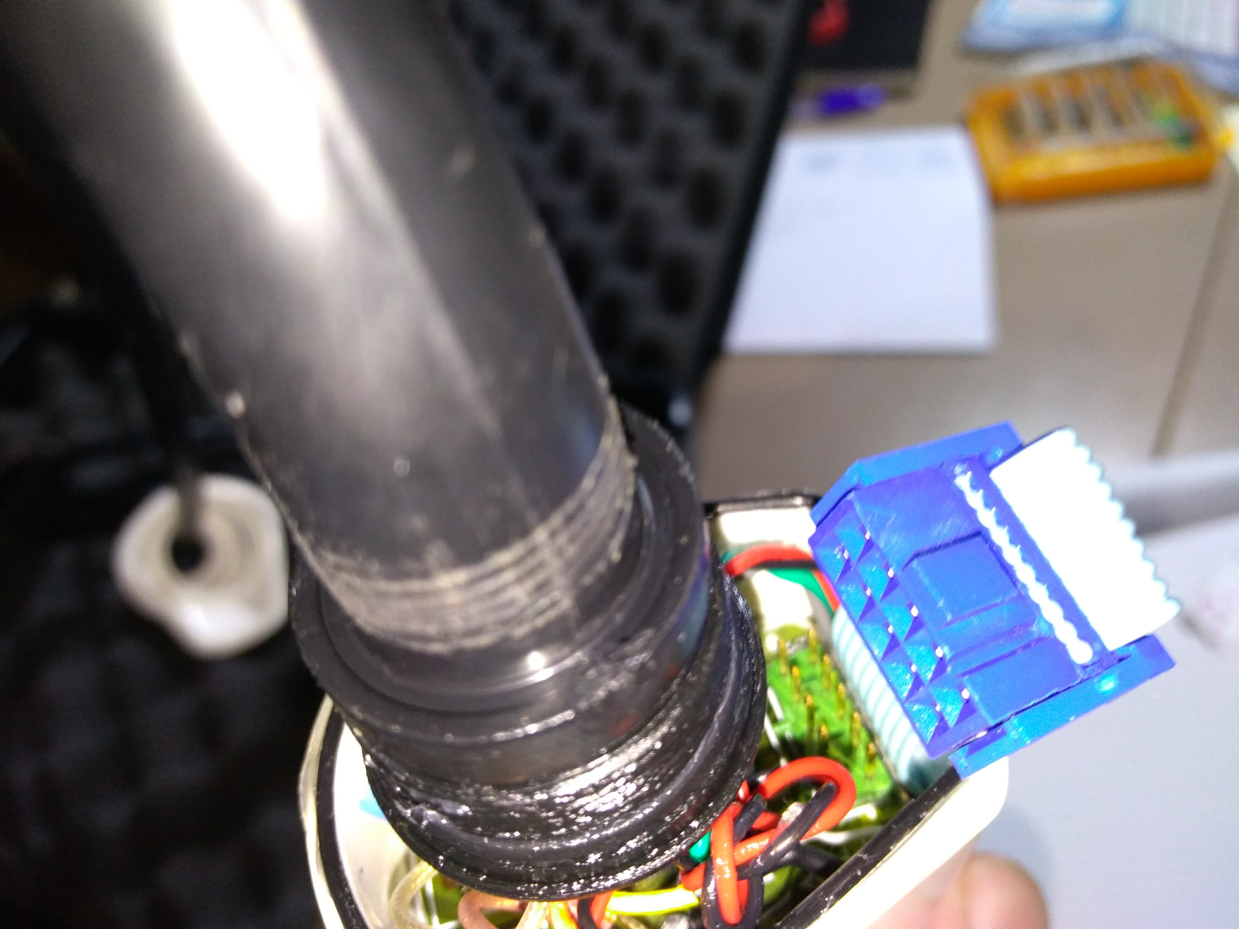
Bit of cables in this small space, including a 5x2 header (what's that?), then 2 shielded coax, and 2 pairs.
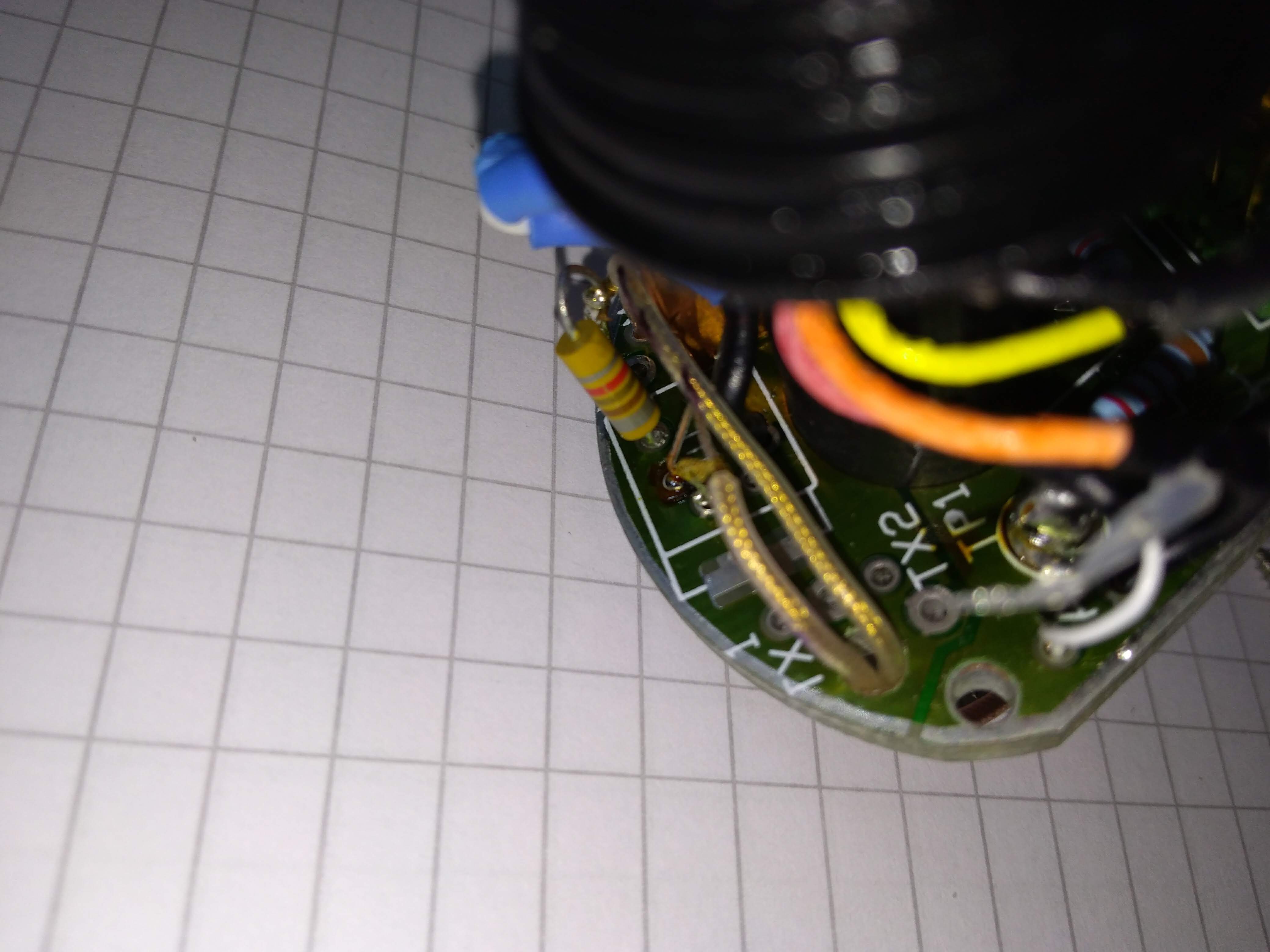
There are 4 screws on the PCB, that we can safely remove. Not much on the PCB itself. Coaxes go into a Tx1 and Tx2 points on the PCB, so I guess that's 2 piezos in the head.
The 5x2 really comes from the motor possibly for the stepper controls, then 2 pairs go to it as well (driving the motor?) and the 2 coax, still possibly for the piezos.
To test!
Automated list of supporting files for the experiment 20180809b
List of files
md
python
Modules
- Probe used: ausonics75
Images of the Experiment
Others
ausonic 7.5MHz probe (category: teardown).
ausonic 7.5MHz probe (category: teardown).
ausonic 7.5MHz probe (category: teardown).
ausonic 7.5MHz probe (category: teardown).
ausonic 7.5MHz probe (category: teardown).
ausonic 7.5MHz probe (category: teardown).
ausonic 7.5MHz probe (category: teardown).
ausonic 7.5MHz probe (category: teardown).
ausonic 7.5MHz probe (category: teardown).
ausonic 7.5MHz probe (category: teardown).
ausonic 7.5MHz probe (category: teardown).
ausonic 7.5MHz probe (category: teardown).
ausonic 7.5MHz probe (category: teardown).
ausonic 7.5MHz probe (category: teardown).