Detailed logs of experiments
2016-08-22-Fantom
20160822 Acquiring a fantom image
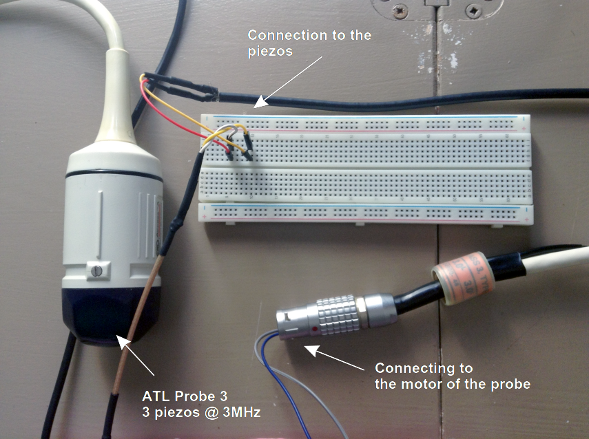
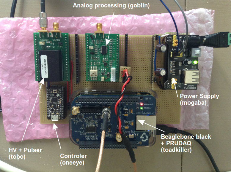
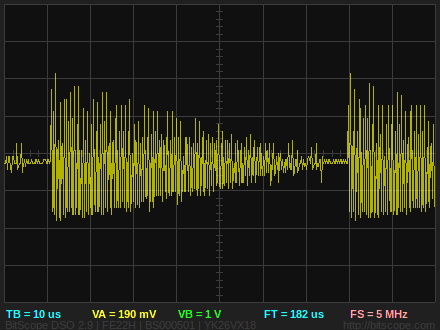
The following acquisition was done with an old mechanical ultrasound probe, along with the pulser module, the analog processing module. The acquisition was done with a beaglebone PRUDAQ at 10Msps. I'm not mentionning the power supply module.
You can download the raw data at using this link.
The raw image
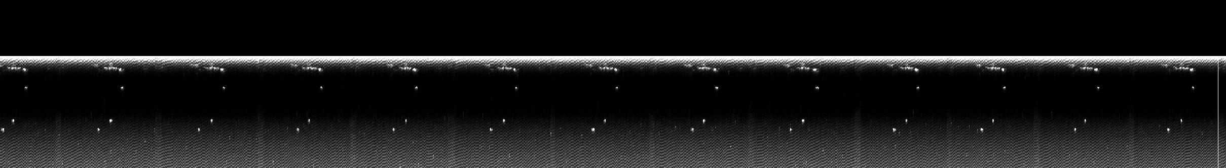
The animated image
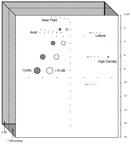
Comparing with the fantom
I guess the points we see are the points on the left hand of the fantom. The top of the fantom is not seen as the near field artifact is at goes till around 2cm (according to the probe specs).
Some comments
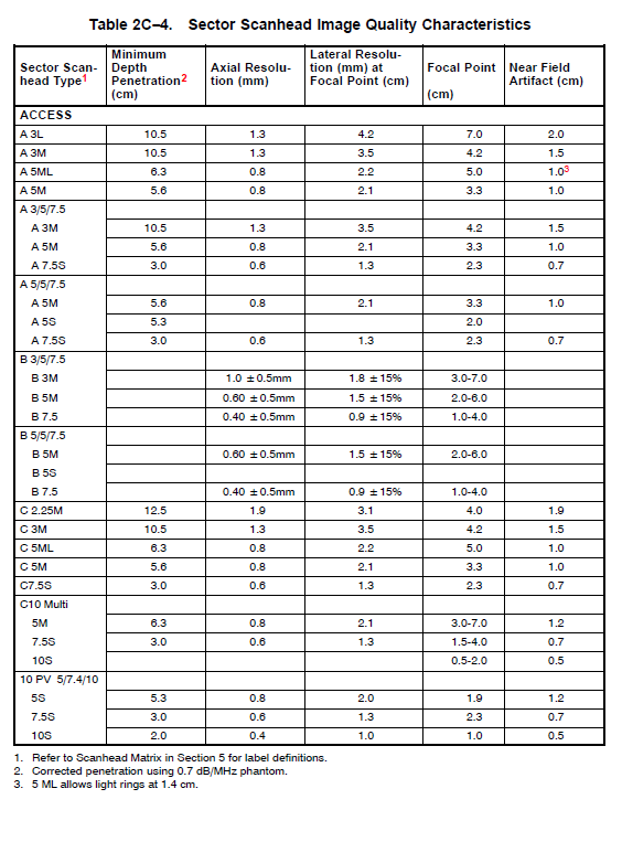
As seen in the list of probes, the probe we've been using has the following characteristics:
- near field artifact till 2cm
- focal point at 7cm
- Lateral resolution of 4.2mm at 7cm depth
- Axial resolution of 1.3mm at focal depth
This matches with what we're seeing.
Annex
Probe details
Setup
2016-09-10-Feather_ADC
Playing with the STM32F205 (Feather WICED ADC)
First tests
Code can be found here.
Testing it with a 10kHz (0-1V) sine gives the following
and with a 10kHz (0-1V) sine:
Not satisfactory.
Digging into the low-level code
Code can be found here.
Sources
http://microcontroleurs.blogspot.fr/2015_07_01_archive.html?view=sidebar interessant!
RCC_ADCPRE_PCLK_DIV_2 can replace ADC_PRE_PCLK2_DIV_2 .. or so it seems
Question
Question is found on github:
I'm trying to see how fast the Feather WICED ADC can go. I've been trying with analogRead(), and at first sight, I'm getting data at around 50ksps. Will be posting the raw data later on to support this.
Now, I've begun digging into the maple ADC and corresponding code, and I've put together a piece of code to test acquisition speed. This code compiles nicely, but doesn't work (nothing on serial). I'm unsure of the reason behind this, and I guess some registers need to be finetuned.
For example, the enumeration for STM32F1 differs from STM32F2, as said by leaflab. However, using ADC_SMPR_1_5 during compilation works, but not the actual ADC_SMPR_3.
Working on this at the moment, but would appreciate if you had some ideas on what I could do next, I'll be updating/documenting the issue in the same time.
Playing with the same code (D+1)
But removing all references to the second ADC (and so .. to the third as well), the code works.
Interfacing the feather to a i2c 128x64 oled display, I can see that it takes around 990 us to get 1000 samples. That's a bit more than 1Msps - and it should be enough to get a signal coming from the emulator.
Moreover, with this working, we can see that the input signal coming from 0 to 3.3V gives 0 to 4095.. as expected. Since the output of Goblin is up to 3.3V, it means I can connect goblin's output to this one, and try to trig on the same trigger as the emulator as well. Will need a level shifter.
Playing with the same code (D+2)
Been putting the trig on the 5V trigger from the pulser. Works better.
Also doing some averaging.. need to check if it really works.
Anyhow, the code works.
It seems like for 2048 points buffer, only 4 full periods of the pulser are present. This pulser working at 300us intervals, this would put the acquisition at 1.7Msps. Need to check what is really the speed of this acquisition.
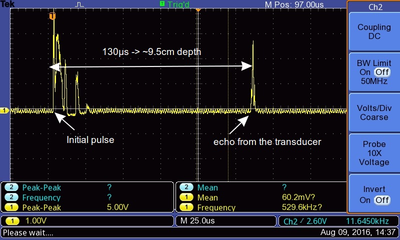
Seeing echoes as well from a real transducer =)
Being a bit more serious
The code is here ADC2UDP-Cleaning.ino.
Testing the speed of acquisition
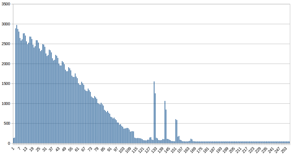
I got 24x128 points (data is here, decimated 128 times: and I see 22.2 decimated points for a period of 300us.
Thats 533 points per period. Since it's a 300us period, the overall acquisition speed is close to 1.776Msps at 12 bits, using only one ADC.
Getting an image with Silent and Goblin
Background
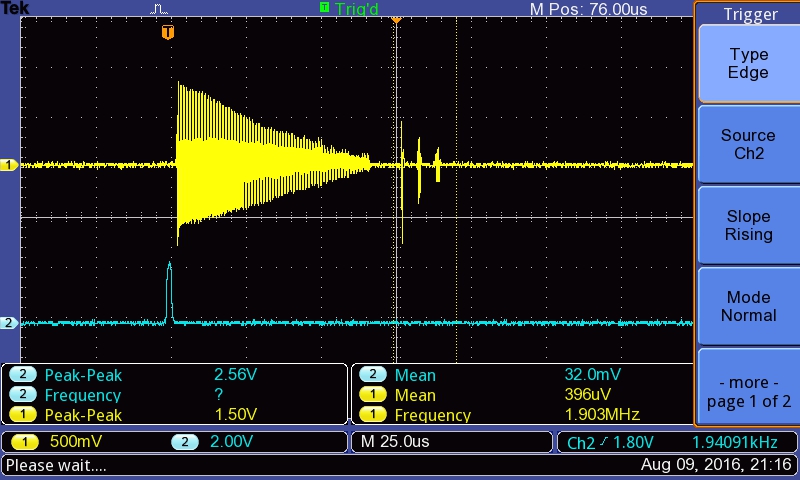
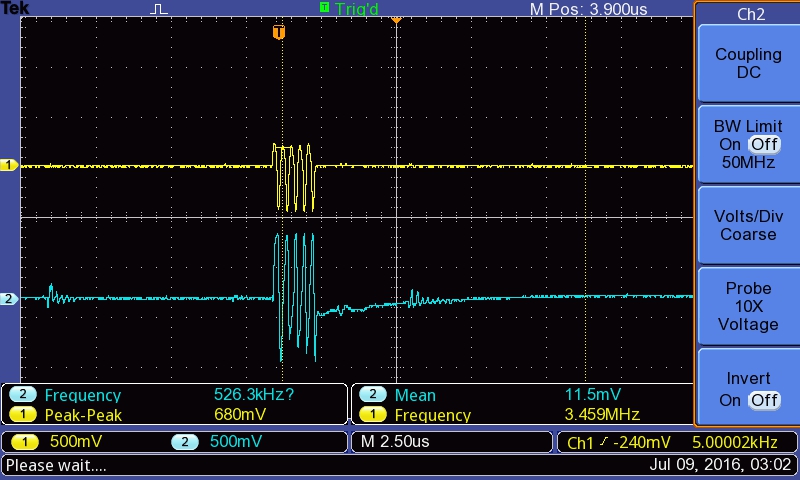
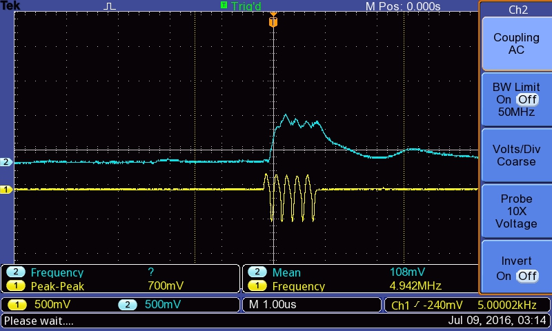
Silent is the emulating module, which emulates a ultrasound piezo. It's output before Goblin, the analog processing module, is as follows:
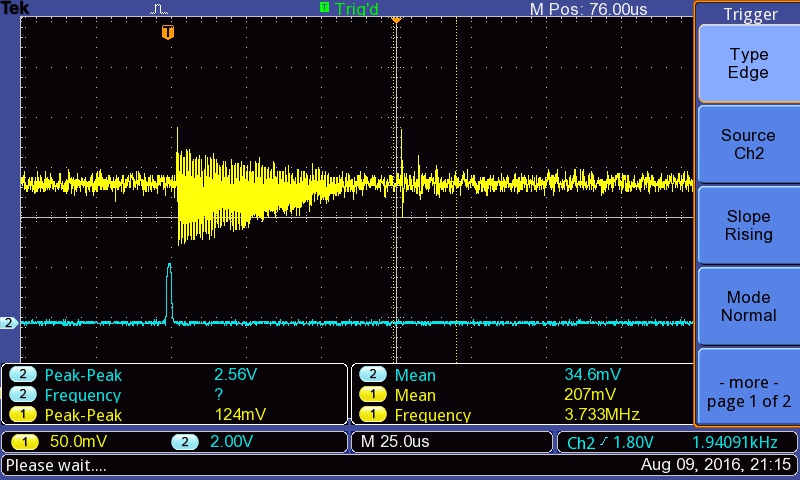
and after
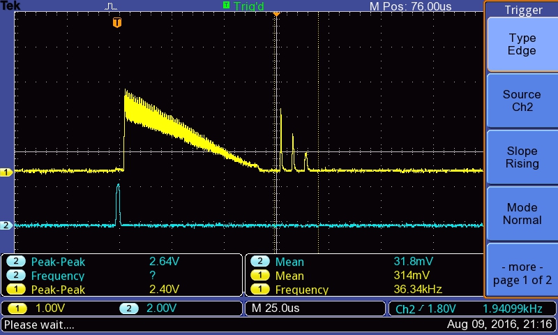
Acquisition
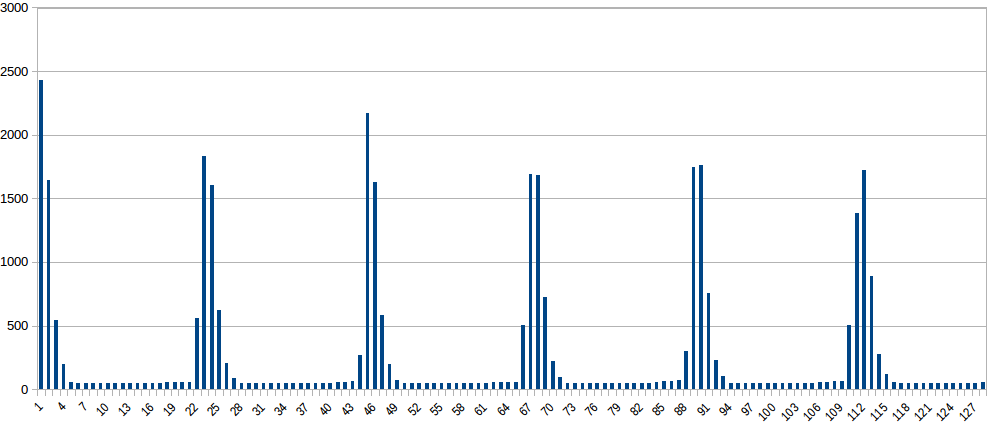
The data was acquired with Croaker through the UDP streaming option. Lines are 128 points long (hence 72us long), and the value is coded over 12 bits, from 0-4095, corresponding to 0-3.3V. Data is here
Comparing with the source signal, it seems that we are late on acquisition: the trigger took some time.
Peaks on the 3 smaller peaks afterwards are on points 82, 88 and 95. That's 6.5 points on average between each, or 3.66 us between each peak. In the config of Silent, we see that each is separated by roughly 7 us. That would mean the ADC speed varies. Needs to be explored.
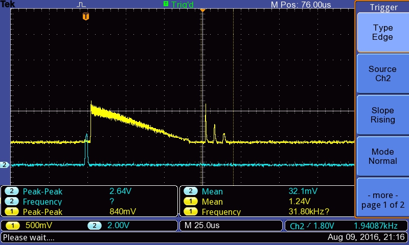
Next steps: getting more juice from the ADCs
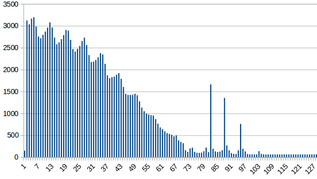
New acquisition is as follows:
The peaks get better resolved. Data is here -and Arduino code is here. Roughly doubling the sampling rate.
- Video of the setup, showing the OLED screen showcasing the signal : https://www.youtube.com/watch?v=iyfDMsgAquI
2016-07-15
Second hands-on with Goblin : an overview
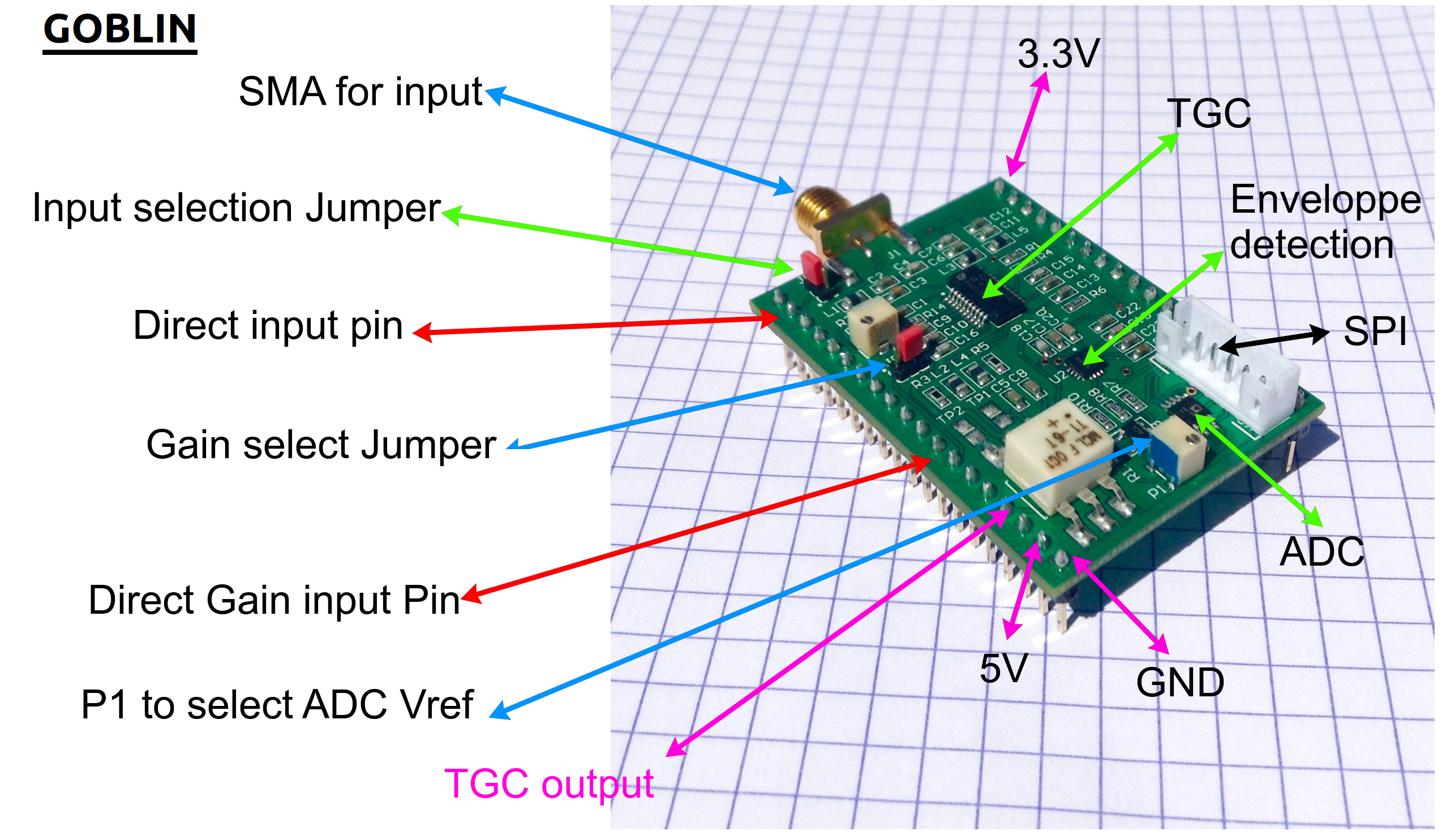
What does it do?
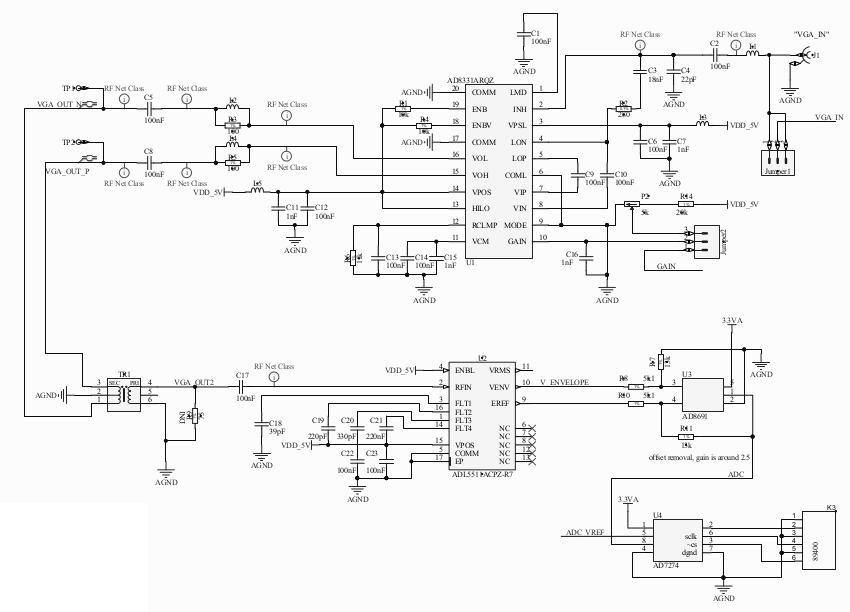
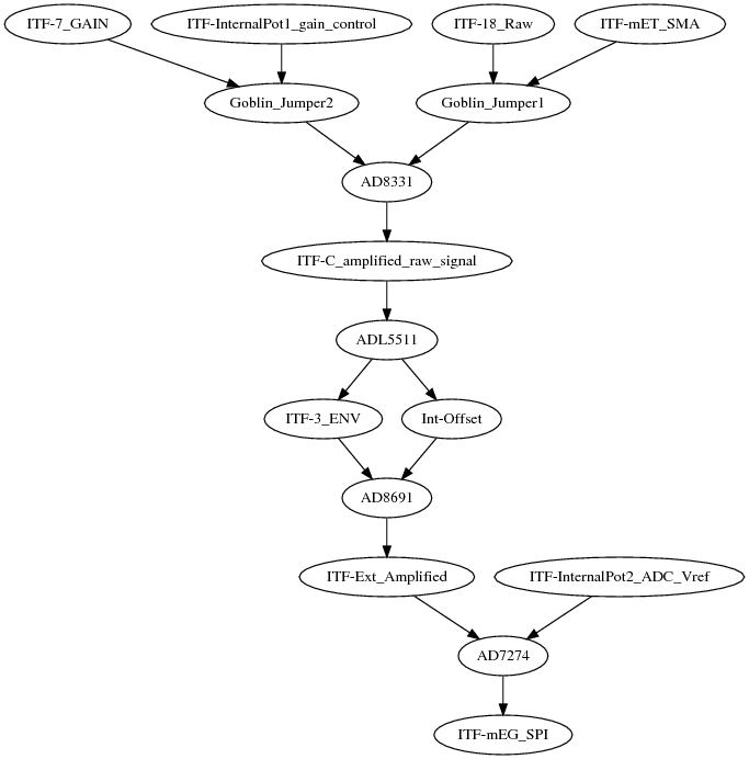
This Goblin board aims at getting a signal, and giving access to key points within the signal processing chain for ultrasound imaging, namely:
- Getting access to a TGC
- Getting the enveloppe of the signal
- Cleaning the signal before feeding in the on-board SPI ADC
All key signals are accessible, and jumpers, as well as pots, enable on-board fine-tuning of the signals. See more details on the testing session, to see the behavior of the board on a oscillo. __Beware, this session had a poor energy supply quality, so the 5V got quite low. The new log, covers it better.
Testing the board using 0.2V in gain input (max can be 1V, that's ~20% gain used)
Just after the TGC : A 60mV signal becomes a 300mV signal.
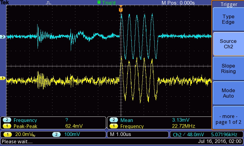
Which becomes, after enveloppe detection, a 400mV enveloppe.
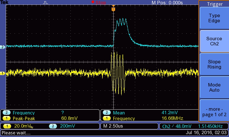
Likewise, a 120mVpp signal becomes a 750mV enveloppe, clean.
View
Detailed view
Principles
2016-08-09
Testing the full setup
The pulser module, Tobo, was received.
Here are the results on the different tracks on the motherboard
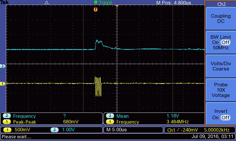
Amplified signal after TGC
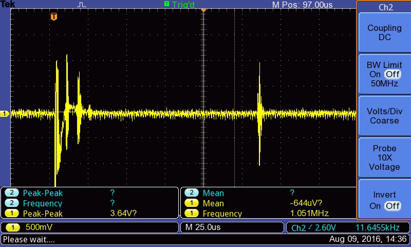
After enveloppe detection
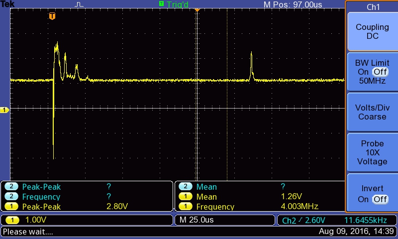
With the final enveloppe
2016-07-08
First hands-on with Goblin : an overview
What does it do?
This Goblin board aims at getting a signal, and giving access to key points within the signal processing chain for ultrasound imaging, namely:
- Getting access to a TGC
- Getting the enveloppe of the signal
- Cleaning the signal before feeding in the on-board SPI ADC
All key signals are accessible, and jumpers, as well as pots, enable on-board fine-tuning of the signals. See more details on the testing session, to see the behavior of the board on a oscillo.
View
Detailed view
Principles
Testing the board
Signal in vs Signal out of the TGC
Trying with different frequencies
At 3 MHz

At 5MHz
At 7.5MHz

At 10MHz

Difference between enveloppe and ADC input?
-> the offset is removed, there's also a small gain (x2).
See below: there's an offset at the enveloppe detection (~RMS), which is removed. Enveloppe is 500mV before, comes at 1V+ afterwards.
Before the AOP
After the AOP

TODO: Table
To know more
Components that have been used
- TGC:
- Enveloppe detection:
- ADC:
TODO =)
2016-08-02
Getting more infos for the code
Already doing some signal preparing:
with the following code
Bibliography
TODO
https://learn.adafruit.com/multi-tasking-the-arduino-part-2/external-interrupts
Remaining
- Timers at https://learn.adafruit.com/multi-tasking-the-arduino-part-2/timers
- https://forums.adafruit.com/viewtopic.php?f=25&t=94390
2016-08-09-SilentPlusTobo
Progress from 20160809a being processed (by goblin) )
- Managed to get the proper code to emit the lines only when PULSE_OFF starts (beginning of the image normally)
- It emits a decreasing signal (enveloppe down) and a couple of pulses
- This was sent through track #18 to Tobo for enveloppe detection.
Results